


920008056
Installation
Unpacking
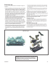
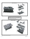
Open the carton and remove the logs and the chassis. Remove
each of the logs by gripping at either end of the log while avoid-
ing any undue pressure. Please note that the logs have been
marked for positive identification.
The carton for all models contains the following: chassis, front
log (#1), rear log (#2), top log (#3), [log (#4), log (#5) are in-
cluded with larger models], 2 screws and a bag of volcanic ash.
Fireplace Preparation
The fireplace needs to be prepared before installing the unit:
A. Turn off the gas supply if the gas line has been run to the
fireplace.
B. WARNING: Before installing logs in fireplace, the chim-
ney flue and firebox must be cleaned of soot, creosote,
ashes and loose paint by a qualified chimney cleaner or
sooting will occur.
Note: If your fireplace has been cleaned using chemicals or
solvents, these products may have been absorbed into the
fireplace hearth and walls and will be burned off during the
initial break-in period.
C. Any outside air ducts and/or ash dumps in the fireplace shall
be permanently closed and sealed at the time of appliance
installation. This will prevent drafts from disturbing the
flames and interfering with complete combustion of the gas
fuel.
Location
When gas logs are to be installed in a fireplace, inspect the
area surrounding it for possible air drafts that may affect the
flames and possibly cause sooting. Such drafts may be caused
by a ceiling fan near the fireplace, a hot air furnace register or
an open door. When burning the logs, carefully observe the
effect of possible drafts on the flames and take appropriate
measures to eliminate them. For example, the ceiling fan may
be cut off, the hot air register closed, etc.
Centrally locate the gas logs in the fireplace deep enough into
the firepit to accomplish an adequate draft (if use as a vented
appliance is planned). Ensure that the front feet of the grate sit
inside the front edge of the fireplace. Be sure fireplace meets
minimum fireplace dimensions.
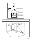
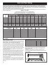
To avoid any movement of the unit during operation, screw
the chassis to the floor of the fireplace using the screws
provided. Failure to do so could cause gas leaks.
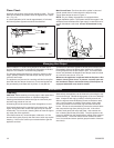
Two brackets are provided. Place brackets over front grate legs
as shown in figure 3. After locating the chassis correctly in the
fireplace, mark the hole positions on the fireplace floor. Drill two
holes approximately 1/2” deep.
Use the two screws to secure the brackets to the fireplace floor,
(Fig. 3)
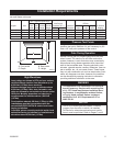
Clearances
NOTE: The following instructions regarding installation clear-
ances and the use and installation of a canopy apply to use
of the appliances as an unvented space heater in permitting
jurisdictions. When installed as a vented decorative gas appli-
ance, the clearances noted below and the use of a heat-deflect
-
ing canopy are not required.
However, it is recommended that these instructions be followed
even when the appliance will be used as a vented decorative
appliance in case local codes change to allow unvented space
heaters or in the event that the flue damper is inadvertently
closed.
Clearances for unvented installation in existing fireplaces,
(jurisdiction permitting)
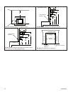
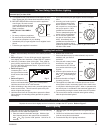
1. Sidewall Clearances: Clearances from the side of the
fireplace opening to any combustible wall should not be less
than 16”. (Fig. 4A)
2. Ceiling Clearances: The ceiling height should not be less
than 42” from the top of the fireplace opening. (Fig. 4A)
3. Mantel Clearances: The use of a canopy* is optional de-
pending on mantel clearances to the fireplace opening and
projection profile.
NOTE: Mantel clearances may differ for each vent-free fire-
box. Refer to the firebox installation instructions for clear
-
ances.
A. Mantel profile: The minimum distance above the fire-
place opening to combustible material projecting 11/8”
(tile moldings, breast boards, etc.) is 15”.
Combustible material projecting 6” (a mantel shelf, for
example) requires a minimum clearance of 19” above the
fireplace opening. Required clearance varies with the
amount of projection. (Fig. 4B)
The mantel profile must fall within the cross-section
shown in figure 4B (if no canopy is used) or 4C (if a
canopy is used).
B. With canopy*: The minimum distance above the fire-
place opening to combustible material projecting 1¹⁄₈" (tile
moldings, breast boards, etc.) is 8".
Combustible material projecting 6" (a mantel shelf, for
example) requires a minimum clearance of 12" above the
fireplace opening. Required clearance varies with the
amount of projection. (Fig. 4C)
C. Heat resistant material: Any heat resistant mate-
rial suitable for a continuous operating temperature of
120°C (248°F) must cover the wall surface directly above
the fireplace opening and extend the full width of the
fireplace opening for a distance of 10” above the opening
if no canopy is used, (8” if a canopy is used). (Figs. 4B
and 4C)
Fig. 3 Use two (2) screws to secure the brackets to the fire-
place floor.