


12
20008056
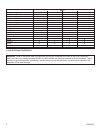
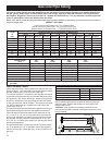
NOTE: To determine the size of the branch gas line from the main gas line to the fireplace, enter the tables below (for
iron pipe or copper tubing) using the distance from the gas meter or second stage regulator to the furthest appliance on
the gas system. Select a pipe or tube diameter which has enough capacity to meet the maximum input requirement of
the fireplace. Regardless, do not use less than 1/2” diameter for the branch line. For any distances required longer than
shown in these tables, refer to the National Fuel Gas Code.
NOTE: There may be a local gas utility requirement specifying a minimum diameter for gas piping. All units require a 1/2 inch pipe con-
nection at the gas valve.
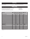
Gas Line Pipe Sizing
CAPACITY OF PIPING
Cubic Feet per Hour based on 0.3” w.c. Pressure Drop
Specific Gravity for Natural Gas - 0.6 (1000 BTU/Cubic Foot)
Specific Gravity for Propane Gas - 1.6 (2550 BTU/Cubic Foot)
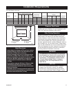
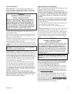
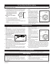
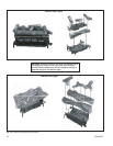
Gas Pressure Check
Check the inlet pressure to the appliance to ensure that it is as
shown in Table 1. Also check the incoming gas pressure where
the field installed gas line connects to the gas logs.
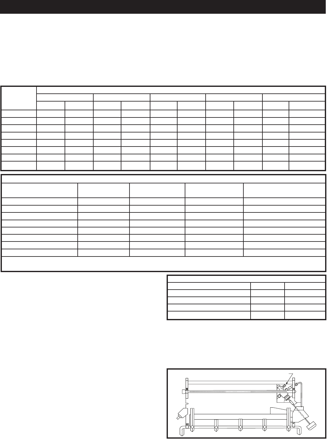
The manifold pressure is controlled by the regulator and should
be checked at the pressure test point located downstream from
the regulator on the control valve body. Access to the pressure
test point is obtained by removing all logs and the heat shield
on the right hand rear side of the base. The pressure test point
1/8” NPT plugged tapping is located on the rear face of the
control body. (Fig. 5)
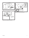
The pressure should be checked with the appliance burning on
high (highest setting) and all other gas appliances turned on.
One must then read the manometer and if pressures are not
10” w.c. for LP or 3.5” w.c. for natural gas, then the inlet pres-
sure must be adjusted or increased until the proper pressures
are attained. If these pressures are greater than 10” w.c. for
LP or 3.5” w.c. for natural gas, contact your gas supplier before
operating the appliance.
The pressure regulator is preset and locked to prevent tamper-
ing. If the pressure is not as specified, replace the regulator
with part # 73332 (for natural gas only), or part # 73333 (for L.P.
gas only).
CAUTION: If the appliance’s operating pressures are not
checked and adjusted, improper combustion may result in soot
being produced.
After measuring the pressure, replace the test point plug and
check for leaks. Replace the control box cover and the two
phillips head screws.
Length Nominal Inches for Iron Pipe Sizes (1,000s BTU/hr)
of 1/2” D 3/4” D 1” D 1
¹⁄₄” D 1¹⁄₂” D
Pipe Natural Propane Natural Propane Natural Propane Natural Propane Natural Propane
20’ 92 143 190 296 350 546 730 1135 1100 1711
30’ 73 115 152 237 285 444 590 918 890 1385
40’ 63 97 130 202 245 380 500 778 760 1183
50’ 56 87 115 179 215 334 440 683 670 1043
60’ 50 79 105 163 196 304 400 622 610 949
70’ 46 71 96 151 180 280 370 576 560 872
90’ 40 61 84 130 160 250 320 497 490 763
100’ 38 59 79 122 150 235 305 474 460 717
Outside Diameter Copper Tubing, Type L (1,000s BTU/hr)
Tubing Length 1/2” 5/8” 3/4” 7/8”
Feet 0.43 0.545 0.666 0.785
10 110 206 348 536
20 76 141 239 368
30 61 114 192 296
40 52 97 164 256
50 46 86 146 224
60 42 78 132 203
80 36 67 113 174
100 32 59 100 154
WARNING: Use only internally tinned copper tubing. If correct copper tubing is not used, tubing can deteriorate and develop
gas leaks.
T126
Test point
10/29/03 djt
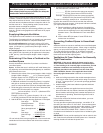
Table 1
Gas Inlet Pressure Natural Propane
Max. 10.5” w.c. 13” w.c.
Normal 7” w.c. 11” w.c.
Min.* 5.5” w.c. 11” w.c.
Regulator Pressure 3.5” w.c. 10.0” w.c.
*Minimum inlet supply pressure for the purpose of input adjustment.
Test Point
T126
Fig. 5 Pressure test point.