


9
Majestic Fireplaces® UVC / UVS Vent-Free Heaters
20000135
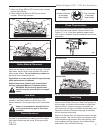
2. Attach wire to switch and install switch into recep-
tacle box. Attach cover plate to switch.
3. Connect wiring to gas valve. (Fig. 10)
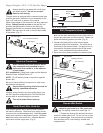
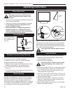
Alternate Switch Location
Remote switch can be installed on either side of the
access door. Simply mount the switch to the switch
bracket provided. Screw the bracket on either side of
the frame, lining up the screws with the pre-punched
holes. (Fig. 11)
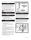
Slide the Heater in Place
With the electrical and wall switch wiring connected,
gently slide or lift the heater to the desired location.
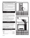
Level and Secure the Heater
If nailing flanges are not already installed, attach
flanges with the screws provided.
Make sure heater is level. Shimming may be required.
Secure heater in place by nailing or screwing through
nailing flanges into framing. NOTE: Be sure to allow
proper space for sheet rock.
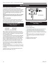
Finishing
CAUTION: All joints between the finished wall and the
heater surround (top and sides) may be sealed only
with non-combustible material. Only noncombustible
material can be applied as facing to the heater surround
(the black painted face).
When finishing the heater, never obstruct or modify the
air inlet/outlet top or bottom grilles in any manner.
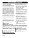
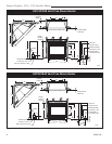
Finish the wall with the material of your choice. Refer to
Page 5, Figure 3 for specific clearances when installing
a combustible mantel or other combustible projection.
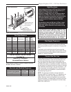
Fig. 10 Remote switch wiring.
P
I
L
O
T
THTP
TP
TH
FP382
REMOTE SWITCH WIRING - NVC
11/20/96
FP382
ON/OFF
Switch
Valve
IF381
NVC -Remote switch bracket
11/20/96
FP381
Fig. 11 Installing remote switch bracket.
Prepunched
Holes