


8
Majestic Fireplaces® UVC / UVS Vent-Free Heaters
20000135
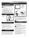
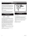
Always check for gas leaks with a mild soap
and water solution. Do not use an open
flame for leak testing.
The gas control is equipped with a captured screw type
pressure test point, therefore it is not necessary to pro-
vide a 1/8" test point up stream of the control.
When using copper or flex connector use only approved
fittings.
Always provide a union so the gas line can
be easily disconnected for burner or fan servicing.
See gas specification for pressure details and ratings.
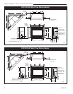
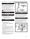
NOTE: If flex connector is used, it must be kept inside
of the heater. (Fig. 7)
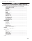
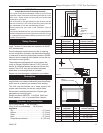
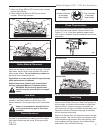
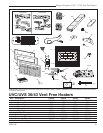
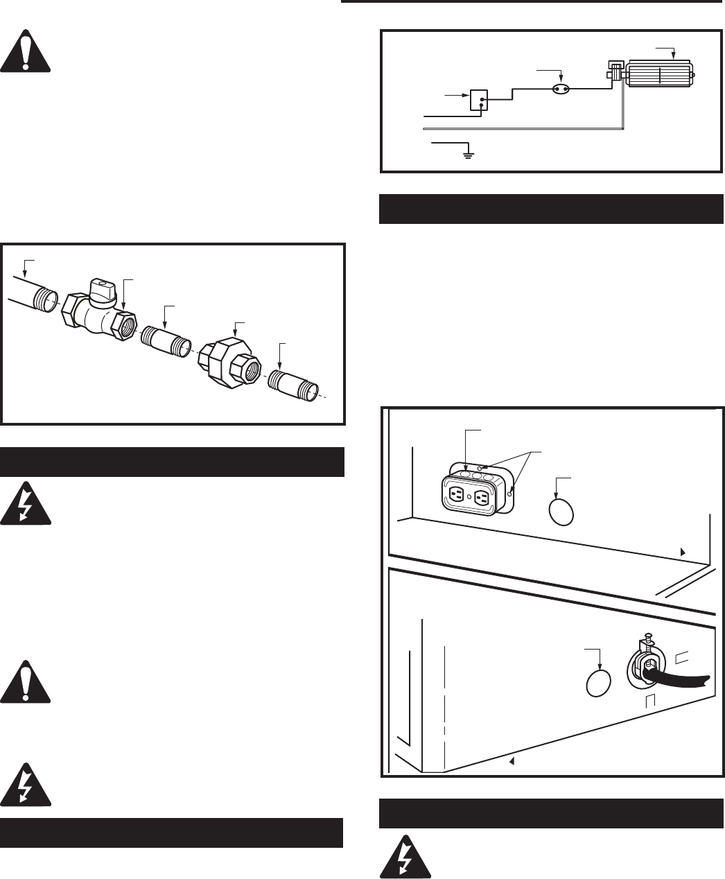
Fig. 8 Junction box (EB-1) hook-up.
FP298
INSTA VENT FREE
EB1 JUNCTION BOX
8/24/96
OUTSIDE
FRONT OF UNIT
INSIDE
FRONT OF UNIT
FP298
Electrical Box
Fastening Screws
Gas Inlet Hole
Gas Inlet Hole
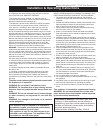
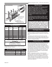
Fig. 8 Wiring diagram.
FP394
FP394
WIRING DIAGRAM
11/20/96
Fan
Temperature
Sensor
Speed
Control
Black
White
Ground
Fig. 7 Typical gas supply installation.
FP297
FP297
INSTA VENT FREE
R MODEL GAS SUPPLY
8/24/96
1/2" Gas Supply
1/2" x 3/8" Shut Off Valve
3/8" Nipple
3/8" Union
3/8"
Nipple
Electrical Connection
When installed, the heater must be electri-
cally connected and grounded in accor-
dance with local codes or, in the absence
of local codes:
U.S. Installations: Follow local codes and the National
Electrical Code, ANSI/NFPA No. 70.
NOTE: 110/120 electric power is required to operate
blower (fan).
Be sure to leave sufficient excess wire in case minor
adjustments are required.
Any electrical re-wiring of this fan must be
done by a qualified electrician.
Whether wiring directly to the fan junction box or into
the EB1 (electrical receptacle box, P/N ZA1200) first
ensure cable is secured using box connector.
Turn off all power before hook-up.
Hard (DIrect) Wire Hook-Up:
First connect ground wire to ground stud located on
the base of either box. Black wire from supply should
connect to the variable speed switch. Alternate speed
switch wire connects to temperature sensor. Alternate
lead from sensor connects to fan. Alternate fan con-
nects back to white supply wire. (Fig. 8)
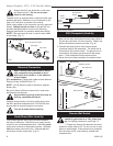
EB1 (Receptacle) Hook-Up
1. Remove 2" knockout. Slide the electrical box back
plate into the back and bottom lances (clips) while fit-
ting the box connector into the knockout. Fasten into
place with fastening screws provided. (Fig. 9)
2. Connect the black positive wire to brass screw
(polarized side) of the receptacle. The white wire is
connected to the chrome screw. The ground wire is
connected to the green ground screw of the recep-
tacle. Fit the receptacle into the electrical box.
3. Screw the cover plate provided to the electrical box.
Remote Wall Switch
CAUTION: Do not wire millivolt remote wall
switch for gas heater to a 120v power sup-
ply. For lighting instructions, see Page 12.
1. Thread wire through the electrical knockout
located on either side of unit. Do not cut wire or insu-
lation on metal edges. Ensure that wire is protected.
Run the other end to a conveniently located wall
receptacle box.