


17
Majestic Fireplaces® UVC / UVS Vent-Free Heaters
20000135
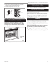
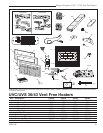
Optional Accessories
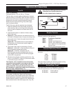
Fan Kit
FK24 Fan Assembly
Fan specifications: 120 volt, 60 Hz, .75 Amps
This fan does not need regular maintenance, however
periodic cleaning is required. Check the area under the
control door and in front of the fan and wipe or vacuum
at least once a month during the operating season.
Should this fan require servicing, the power supply
must be disconnected.
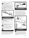
The FK-24 comes with the electrical cord attached.
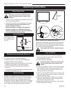
1. Slide fan assembly from the left side into the fire-
place opening, line up mounting holes with screw
studs on back of fireplace and fasten with #10-24
hex nuts.
2. Install thermal sensor on bottom of firebox using
#10-24 hex nuts.
3. (Option A) - Place electronic fan speed control box
on bottom of fireplace base, lining up mounting holes
with screw studs. Fasten fan speed control box with
#10-24 hex nuts.
(Option B) - The speed control can be installed in
an electrical box at normal wall switch height for
convenient access.
4. The power supply may be connected in 2 ways:
Method A - route the 6' (1.8m) lead fitted to the unit
to a conveniently located wall socket.
Method B - If the EB-1 receptacle box (Pt.
#ZA1200) was correctly connected when the unit
was installed, the fan lead can be directly plugged
into the EB-1 plug socket.
5. Whether wiring directly to the fan junction box, (Op
-
tion A) or into the EB-1 (Option B), first ensure cable
is secured using box connector.
The fireplace, when installed must be electrically
connected and grounded in accordance with local
codes or, in the absence of local codes, with the
current CSA C22.1 Canadian Electrical Code or for
US installations, follow local codes and the National
Electrical Code, ANSI/NFPA No. 70.
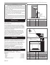
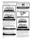
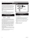
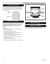
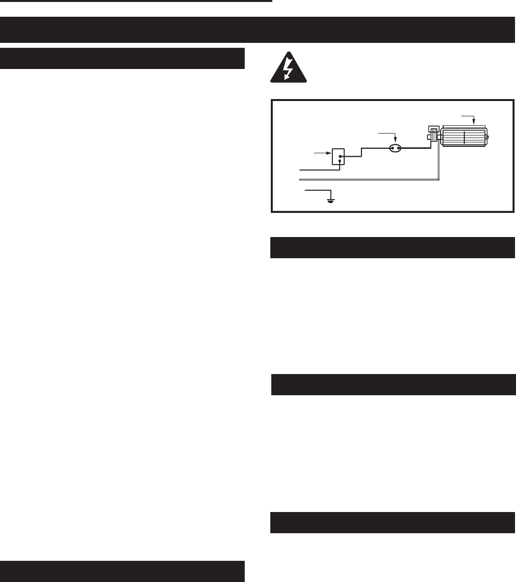
Hard (Direct) Wire Hook-Up
First connect the ground wire to the ground stud located
on the base of either box. Black wire from supply
should connect to the variable speed switch. Alternate
speed switch wire connects to temperature sensor. Al-
ternate lead from sensor connects to fan. Alternate fan
lead connects back to the white supply wire. (Fig. 20)
Any electrical rewiring of this fan must be
completed by a qualified electrician.
Turn off all power before hook-up.
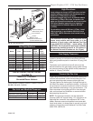
FP394
WIRING DIAGRAM
11/20/96
Fan
Temperature
Sensor
Speed
Control
Black
White
Ground
FP394
Fig. 20 FK-24 wiring.
Remote Controls
Optional remote control units are available to control
different functions of the appliance.
Model Function(s) Controlled
MRC1 ON/OFF
MRC2 ON/OFF and Temperature
MRC3 ON/OFF and Temperature control
with a digital and a programmable
24 hour clock
IMT Wall mounted thermostat control
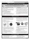
Ceramic Refractory Panels
Ceramic refractory panels are available to line the fire-
box area.
Unit Kit Model
UVC36 UV36CR
UVS36 UV36CR
UVC43 UV43CR
UVS43 UV43CR
Take care when handling the refractory panels as they
are fragile until held in place and supported.
Arched Door Front
The arched door front kit is designed to visually en-
hance the appearance of the UVC36 fireplace only.
DV36ADKP Polished Brass
DV36ADKA Antique Brass