


11
Majestic Fireplaces® UVC / UVS Vent-Free Heaters
20000135
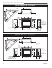
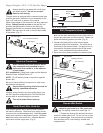
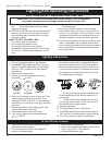
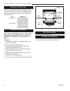
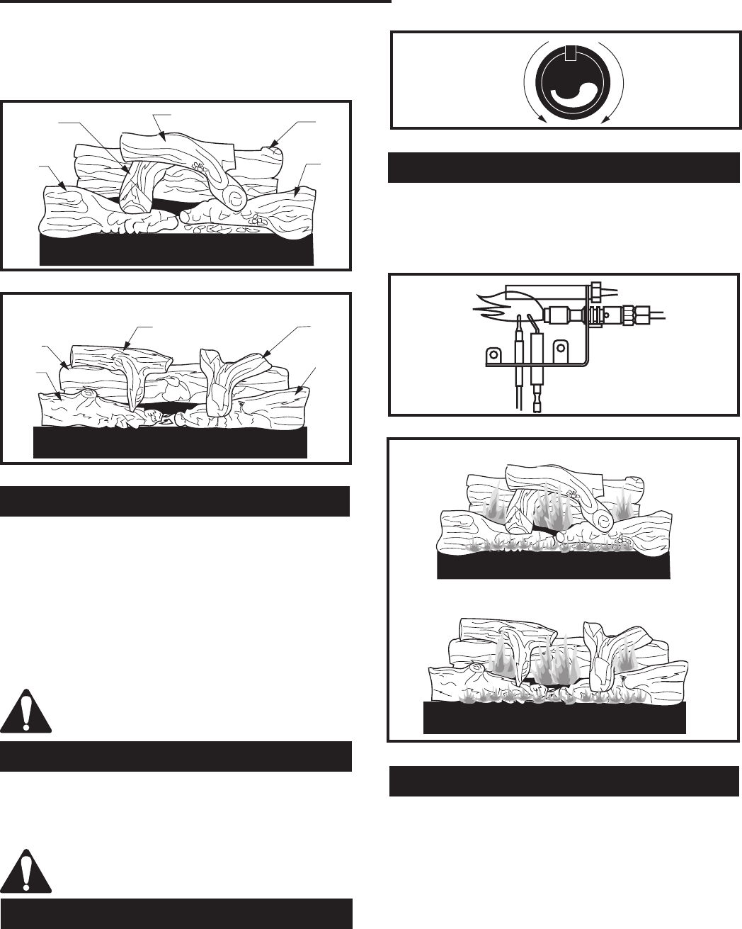
7. Place top left log (BE9 or BF11) onto locator notches.
Ensure log is secure.
8. Place top right log (BE10 or BF12) onto locator
notches. Ensure log is secure.
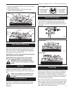
Ember Material Placement
Separate the ember material into small pieces and
place onto the burner in front of the front logs. Do NOT
pack down, leave in fluffy, loose condition for most re-
alistic ember effects. Do not install more embers on
the burner than come with the unit.
Application of excess loose material may adversely
affect performance of theheater.
Replacement loose embers must be purchased
through authorized Majestic Fireplaces dealers.
WARNING: All previously applied loose
material must be removed prior to reappli-
cation.
Lava Rock
The lava rock provided with this fireplace must be
placed on the firebox bottom on either side of the
burner assembly. Do not place lava rock in combustion
pan.
Under no circumstances should this lava
rock be placed on any part of the burner
assembly.
LG131
UVC/UVS36 LOGS
9/8/00 djt
BE10
BE8
BE7
BE6
BE9
LG131
Fig. 14 UVC/UVS36 log placement.
LG132
UVC/UVS43
Log placement
9/8/00 djt
BF11
BF8
BF9
BF10
BF12
LG132
Fig. 15 UVC/UVS43 log placement.
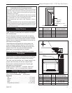
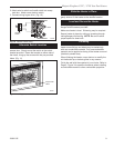
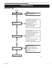
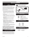
Flame Adjustment
For fireplaces equipped with HI/LO valves, flame ad-
justment is accomplished by rotating the HI/LO adjust-
ment knob located near the center of the gas control.
(Fig. 16)
LO
HI
Turn
counterclockwise
to decrease
flame height
Turn clockwise
to increase
flame height
HV102
Honeywell hi/lo knob
4/5/99 djt
Fig. 16 Flame adjustment knob for Honeywell Valve.
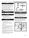
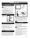
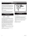
Flame Characteristics
It is important to periodically perform a visual check
of the pilot and burner flames. Compare them to the
Figures 17 or 18. If the flame patterns appear abnor-
mal, contact a qualified service provider for service and
adjustment.
Fig. 18 Approximate flame heights for each model.
UVC36/UVS43
UVC43/UVS43
LG131
UVC/UVS36 LOGS
9/8/00 djt
LG134
UVC/UVS43
Log placement flames
9/8/00 djt
LG133
LG134
IF449
NOVA SIT PILOT
UVC
2/14/97
FP449
Fig. 17 Correct pilot flame pattern.
First Firing
Upon completing the gas line connection, a small
amount of air will be in the lines. When first lighting unit
with pilot light, it will take a few minutes to purge them-
selves of this air. Once the purging is complete, the
pilot and burner will light and operate as indicated in the
instruction manual. Subsequent lightings of the heater
will not require such purging.
When lit for the first time, the appliance will emit a slight
odor for awhile. This is due to paint and lubricants used
in the manufacturing process. After each lighting, vapor
may condense and fog the glass; this moisture disap-
pears within a few minutes of burning.