


8
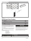
UV36 Vent-Free Firebox
20007446
T234
finishing w/facing
2/04
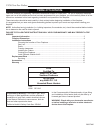
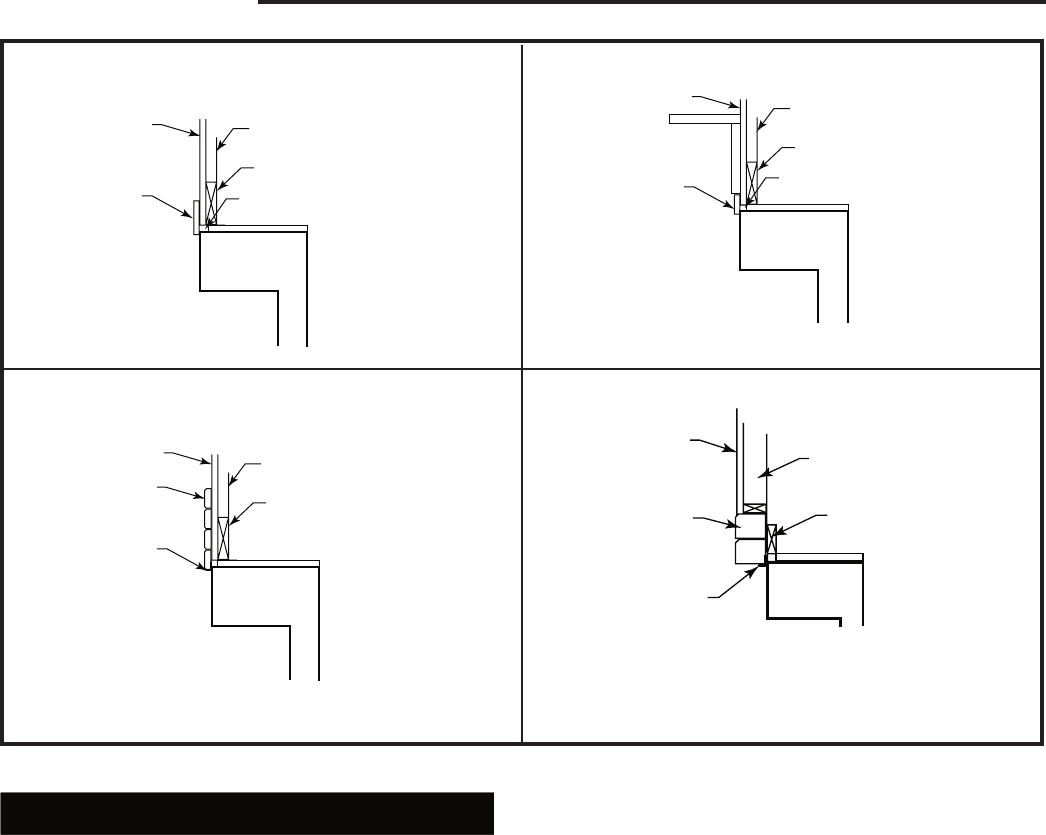
Finished Wall
Noncombustible
Decorative Covering
Stud
Header
Must be enclosed with a
noncombustible material.
T234
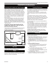
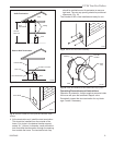
6a Wallboard with Marble, Slate or Tile Facing
T235
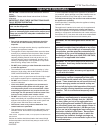
finishing w/facing,
and mantel
2/04
Finished Wall
Noncombustible
Decorative Cover-
ing
Stud
Header
Must be enclosed with a
noncombustible material.
The bottom mantel projection must be located a mini-
mum of 9” above the fireplace opening. (Fig. 5b)
T235
6c Wallboard with Facing and Mantel
T236
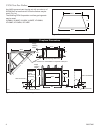
brick or stone
facing
2/04
Finished Wall
Stud
Header
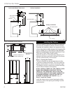
6b Brick or Stone Facing
T236
Brick or
Stone Facing
Steel Lintel*
T237
facing not flush
2/04
6d Wallboard with Facing-Not Flush
Brick or
Stone Facing
Finished Wall
Stud
Header
Steel Lintel*
T237
*Brick or stone facings lid up on the face of the fireplace must be
sealed to it with a steel lintel. Attach the lintel to the fireplace face
with sheet metal screws and seal it with a heat resistant sealer.
The projecting portion of the lintel should be imbedded in a mortar
joint or mortared to the bottom of the facing. The lintel acts as a
support and a firestop.
Fig. 5 Finishing options.
Install Optional Outside Air Kit
The AKU3 Outside Air Kit can be installed to bring com-
bustion air to the heated room air. The air that is drawn
into the heated room air from outside the home or un-
heated area helps relieve the pressure in the home.
The duct termination should be located so it is exposed
to an out-of-doors opening at least 100 square inches.
If the duct termination must be located in a crawl space
or basement, be sure the termination area has 100
square inches of ventilation opening to outside air.
The duct termination must be located so it does not
compete for air flow with exhaust fans, gas vent hoods
or other air consuming devices or appliances. It must
not be obstructed by rafters, insulation materials or
other obstructions. The less restrictive the air supply,
the better the outside air kits will perform.
It is good practice to protect your hands and eyes
during installation by wearing work gloves and safety
glasses.
CAUTION: Do not install termination into a garage
or other area that could contain flammable liquids
or fumes, or into an attic space.
Installation Instructions
Determine the location of the fireplace as described
in the fireplace installation manual. Then plan location
of the duct termination and the route of the duct run
between the fireplace and the duct termination.
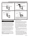
Duct run must be limited to a maximum distance of 40’
(12.2m) from the fireplace pipe collar to duct termina-
tion. This will provide the least restriction to air flow. No
more than four (4) 90° elbows can be used. Duct run
may be horizontal, vertical, inclined or any combina-
tion of these. (Fig. 7) You are now ready to install the
Outside Air Kit.
1. Remove the screws retaining the outside air cover
-
plate, if provided. (Located on the left side of front
open units, on backside of multisided units.) Discard
coverplate. (Fig. 8)
2. Secure the inlet collar assembly to the outer casing
with four screws (not provided). (Fig. 9)
3. Slide the duct over the collar and attach the duct
to the collar using the plastic tie straps or three (3)
screws (screws not provided). Continue attaching
the ducting together using three (3) screws at each
joint until you have installed sufficient duct to arrive
at your duct termination locations.