


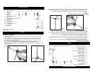
ASSEMBLY OF BLADE AND GRILLS (#1-7)
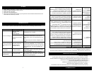
1. Fig. 5A:
Remove and discard the plastic sleeve on the motor shaft (Part #7). Position the rear grille (Part
#6) against the front of the motor housing (Part #8) through the motor shaft (Part #7). Ensure that
the handle at the back of grille is facing up and that all guiding pegs on the motor housing are
lined up with cutouts on the rear grille (Part #6).
Fig. 5B:
Secure the rear grille (Part #6) into place with the plastic nut (Part #5). Fasten the plastic nut (Part
#5) firmly onto the motor housing (Part #8) by tightening it in a CLOCKWISE direction.
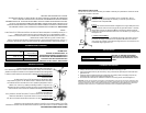
2. Fig. 6A:
Install the fan blade (Part #4) onto the motor shaft (Part #7) with the cutouts fitted.
Fig. 6B:
Place spinner (Part #3) on the motor shaft (Part #7) after the blade (Part #4).
Fasten into place by tightening the spinner (Part #3) COUNTER-CLOCKWISE direction.
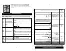
3. Fig. 7A:
On the bottom of the plastic grille band (Part #1) loosen, BUT DO NOT REMOVE the setting
screw with a screwdriver.
Fig. 7B:
Hook the band around the rim of the rear grille (Part #6) and note there are two thin rails inside of
the plastic grille band (Part #1). Ensure the entire rim of rear grille is on the further rail. Then put
the front grille to the band and carefully click the entire rim of front grille into the front rail of the
band. Ensure the setting screw is centered at the bottom of the grilles.
Fig. 5 Fig. 6
Fig. 7A Fig. 7B
5A
5
B
6
A
6
B
4
4
cara hacia arriba y de que todas las clavijas en el motor queden alineadas con las hendiduras en
la rejilla posterior (Pieza #6).
Fig. 5B:
Asegure la rejilla posterior (Pieza #6) en su lugar utilizando la tuerca plástica (Pieza #5). Ajuste la
tuerca plástica (Pieza #5) firmemente sobre el motor (Pieza #8) ajustándola en el SENTIDO DE
LAS AGUJAS DEL RELOJ.
2. Fig. 6A:
Instale las aspas del ventilador (Pieza #4) sobre el fuste del motor (Pieza #7) encajando las
hendiduras.
Fig. 6B:
Coloque el girador (Pieza #3) en el fuste del motor (Pieza #7) después de las aspas (Pieza #4).
Asegure en su lugar ajustando el girador (Pieza #3) en el SENTIDO CONTRARIO A LAS
AGUJAS DEL RELOJ.
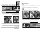
3. Fig. 7A:
En la parte inferior de la faja de la rejilla de plástico (Pieza #1), suelte, PERO NO RETIRE, el
tornillo de fijación con un destornillador.
Fig. 7B:
Enganche la faja alrededor del borde de la rejilla posterior (Pieza #6). Preste atención a que hay dos
canaletas delgadas en la parte interior de la faja de la rejilla de plástico (Pieza #1). Asegúrese de que el
borde completo de la rejilla de plástico quede dentro de la canaleta interior. Luego coloque la rejilla
delantera dentro de la faja y con cuidado enganche el borde completo de la rejilla delantera dentro de la
canaleta delantera de la faja. Asegúrese de que el tornillo de fijación quede centrado en la parte inferior
de las rejillas.
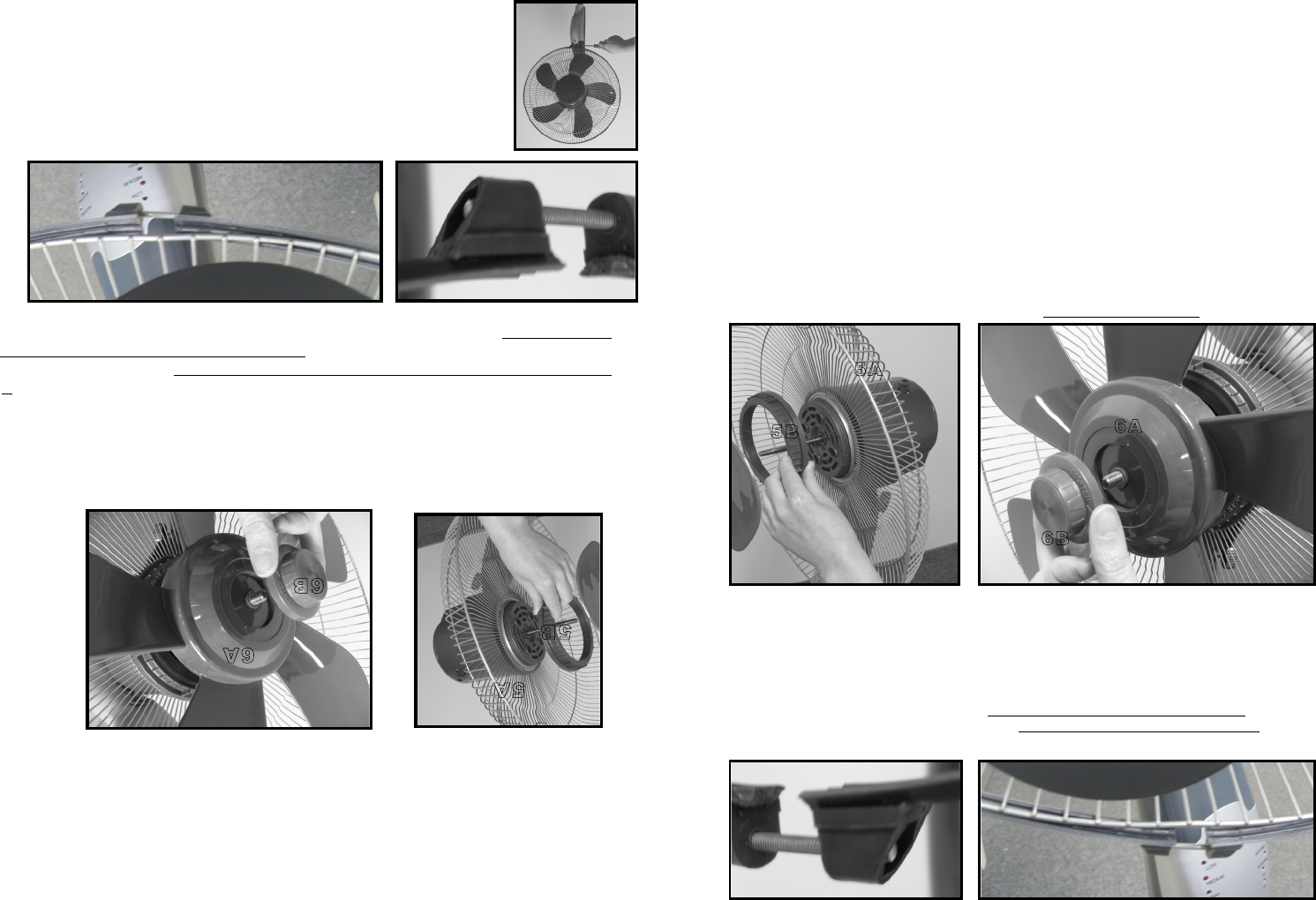
4. Fig. 8: Ajuste la faja para sostener y mantener juntas ambas rejillas (Piezas
#2 y #6). Utilice una mano para sostener las dos rejillas juntas (Piezas #2 y #6)
y la otra para ajustar el tornillo en la faja de la rejilla de plástico (Pieza #1).
Fig. 5
Fig. 6
5A
5
B
6
A
6
B
Fig. 7A
Fig. 7B