


12
107434
VENT-FREE NATURAL GAS PEDESTAL STOVE
For more information, visit www.desatech.com
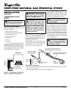
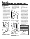
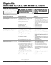
Red
Variable
Fan Switch
Fan Switch
(N.O.)
Green
White
On
110/115
V.A.C.
Blower
Motor
Black
Off
1
2
Black
Blue
INSTALLATION
Continued
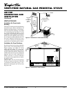
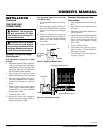
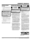
11. Remove three screws and cover plate
from center of firebox back panel.
Keep screws but discard cover plate
(see Figure 17).
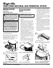
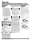
12. Locate thermostatic switch/cover plate
assembly and wire harness supplied
with blower. Attach wire harness ter-
minals to terminals on thermostatic
switch. Push firmly. Make sure the bot-
tom hole of cover is on the opposite side
from the wire harness (see Figure 18).
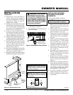
13. Feed terminal ends of wire harness into
the hole in firebox back panel from
front of firebox. Pull the ends of the
harness to the top of firebox near
blower (see Figure 19).
14. Align holes in the switch/cover assem-
bly with holes in firebox back panel.
Using 3 screws from step 11, attach
assembly to firebox back panel. Tighten
screws firmly (see Figure 19).
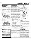
15. Working from the rear of the stove,
place entire power cord, including
speed control housing, in lower control
compartment (see Figure 20).
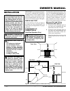
Power
Cord
Speed Control
Housing
Control
Knob
Figure 20 - Connecting Switch, Blower,
and Speed Control Wires
120 Vac. 60 Hz. 90 Amps
DESA International, Bowling Green, KY
WARNING: Never attempt to service heater while it
is plugged in, operating, or hot. Burns and electrical
shock could result. Only a qualified service person
should service or repair heater.
If any of the original wire as supplied with the appliance must be
replaced, it must be replaced with 105°C wire or it’s equivalent.
WARNING: Label all wires prior to disconnection
when servicing controls. Wiring errors can cause im-
proper and dangerous operation. Verify proper opera-
tion after servicing.
Wiring
Diagram
Decal
Figure 18 - Attaching Wire Harness to
Thermostatic Switch and Cover Assembly
Thermostatic
Switch
Mounted to
Cover
Wire Harness
Lower Hole
Figure 19 - Assembling Thermostatic
Switch and Cover to Firebox Back Panel
Thermostatic
Switch
Mounted to
Cover
Wire Harness
Hole in Firebox
Back Panel
Screws
16. Route ends of 3-wire power cord up from
the lower control compartment through
the plastic bushing, then up to the upper
cavity of stove (see Figure 20).
17. Connect white wire from speed control
to either terminal on blower motor (see
Figure 20). Push firmly.
Wire Harness
Blower
Red
Switch
Wire
Green
Ground
Wire
Ground
Wire Screw
White Speed
Control Wire
Black
Speed
Control
Wire
Blue
Switch
Wire
Figure 17 - Removing Cover Plate
Cover
Plate
Firebox Back Panel
Screws
18. Connect the black wire from speed con-
trol to blue wire on switch/cover assem-
bly (see Figure 20).
19. Connect red wire from switch/cover
assembly to remaining terminal on
blower motor (see Figure 20). Push
firmly.
20. Attach green wire from speed control
to front tab of blower housing using
screw provided (see Figure 20). Tighten
securely.
21. Using the four screws previously re-
moved, mount blower assembly to
stove by reattaching blower brackets to
rear panel (see Figure 14, page 10).
Tighten screws securely.
22. Install plastic control knob onto output
shaft of speed control housing (see Fig-
ure 20). Place speed control housing just
inside control compartment door in front
of stove (see Figure 16, page 11).
23. Using two screws provided in blower
kit, mount blower speed control hous-
ing to mounting tab in left side of lower
control compartment (see Figure 16,
page 11).
24. Check to make sure that the power cord is
completely clear of blower wheel and there
are no foreign objects in blower wheel.
25. Carefully replace stove top panel. Align
holes and replace six screws removed
in step 1, page 11. Slide top trim over
sides of top panel. Attach with 2 screws
removed in step 1, page 11.