


10
107434
VENT-FREE NATURAL GAS PEDESTAL STOVE
For more information, visit www.desatech.com
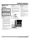
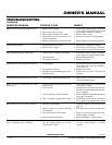
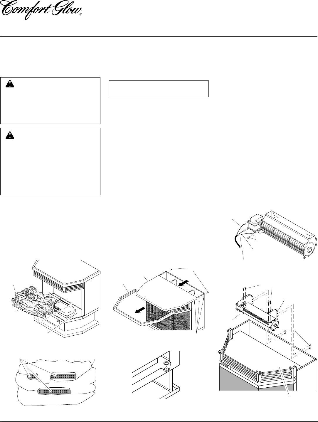
Black Powercord Wire
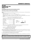
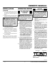
Figure 13 - Removing Wires from Blower
Screw
Green
Ground Wire
White
Powercord
Wire
O
F
F
P
I
L
O
T
O
N
H
I
L
O
WARNING: Failure to position
the parts in accordance with these
diagrams or failure to use only
parts specifically approved with
this heater may result in property
damage or personal injury.
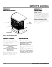
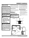
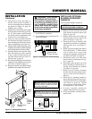
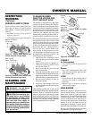
INSTALLING LOGS
It is very important to install the logs exactly
as instructed. Do not modify logs. Only use
logs supplied with heater.
Place one-piece log set on grate to fit as
illustrated in Figure 10. Make sure log sits
flat on firebox floor (see Figure 9).
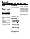
IMPORTANT:
Make sure log does not cover
any burner ports (see Figure 10).
CAUTION: After installation and
periodically thereafter, check to en-
sure that no flame comes in contact
with any log. With the heater set to
High, check to see if flames contact
any log. If so, reposition logs ac-
cording to the log installation in-
structions in this manual. Flames
contacting logs will create soot.
Figure 9 - Installing One-Piece Log Set
One Piece
Log Set
Firebox Floor
Figure 10 - Installing One-Piece Log set
(Top View)
One Piece Log Set
Burner Ports
INSTALLATION
Continued
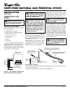
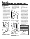
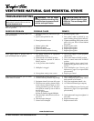
Figure 11 - Removing Stove Top Panel
Figure 12 - Installing Bushing
Figure 14 - Removing Blower Brackets
from Stove and Attaching to Blower
Blower
Blower
Bracket
Firebox Top
Top
Trim
Screws
Top Panel
Screws
Screws
INSTALLING OPTIONAL
BLOWER ACCESSORY
GA3750
Tools required: Phillips screwdriver
NOTICE: Shut off gas heater during
the following blower installation.
1. Remove 2 screws from rear tabs on top
trim. Pull trim forward to remove (see
Figure 11).
2. Remove top panel of stove by remov-
ing three screws from under top lip on
each side of stove (see Figure 11).
3. Facing front of stove, carefully slide top
panel forward until it is completely re-
moved from stove (see Figure 11).
4. Install one plastic bushing provided in
blower kit into the 1
1
/2" hole in the left
rear of firebox floor. Access hole
through the rectangular opening in the
rear panel (see Figure 12).
5. Disconnect power cord wires from blower
motor (if connected) (see Figure 13).
6. Disconnect green ground wire from
blower housing (if connected) by re-
moving screw holding wire terminal
(see Figure 13).
7. Remove the two blower mounting
brackets from the rear panel by remov-
ing two screws each (see Figure 14).
8. Attach the two mounting brackets to
blower housing using four screws pro-
vided in blower kit (2 for each bracket)
(see Figure 14). Tighten screws se-
curely. Place blower assembly tempo-
rarily on top of firebox.
9. Working from the rear of the stove,
place entire power cord, including
speed control housing, in lower control
compartment.
10. Route ends of 3-wire power cord up from
the lower control compartment through
the plastic bushing, then up to the upper
cavity of stove (see Figure 15, page 11).
11. Attach the terminal ends of the white
and black power cord wires to the ter-
minals on the blower motor (see Fig-
ure 12). Push firmly.
12. Attach the terminal end of the green
power cord wire to the front tab of the
blower housing using screw provided
(see Figure 13).
Screws