


21
105983
OWNER’S MANUAL
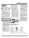
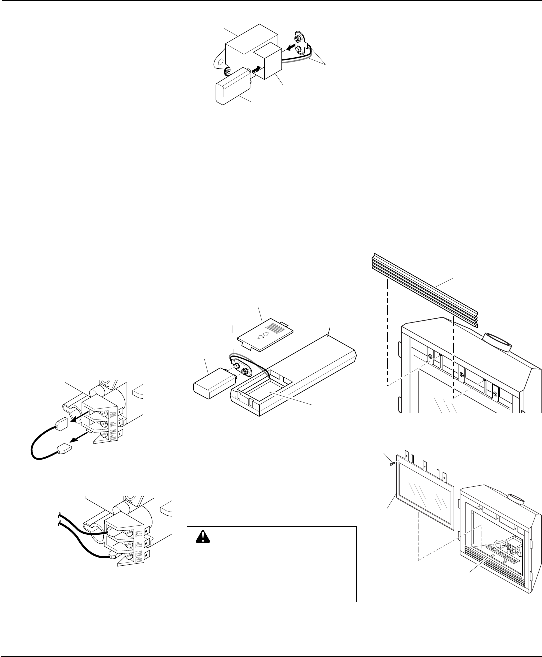
REMOVING/REPLACING
GLASS DOOR
CAUTION: Do not operate this
fireplace with a broken glass door
panel or without the glass door
panel securely in place. For re-
placement part information see
Replacement Parts
, page 31.
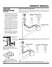
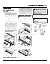
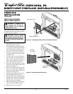
Figure 45 - Removing/Replacing Glass Door
Figure 44 - Removing Top Louver Panel
You must remove glass door to install op-
tional brick liners, logs, lava rock, and em-
ber material.
FIREPLACE
INSTALLATION
Continued
Top Louver
Panel
Glass
Door
Assembly
Screw
Lower Bracket for
Glass Door Assembly
1. Remove the upper louver panel by lift-
ing upward and out (see Figure 44).
2. Remove the screws from the three tabs
at the top of the glass door while hold-
ing door securely keeping it from fall-
ing forward.
3. Grasp door by both sides and ease it
upward off of the lower bracket (see
Figure 45).
4. To replace glass door, follow the above
instructions in reverse.
Attaching Magnetic Decorative
Brass Strips
(Optional Installation)
Before attaching strips to fireplace, remove
plastic film from brass pieces. After install-
ing door, attach these strips to the top and
bottom of glass door frame.
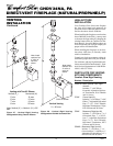
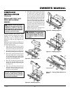
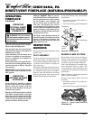
Installing Remote Receiver
1. Open bottom louver and locate the
switch bracket on the left.
2. Unscrew the switch bracket. Lean
bracket forward so you are able to ac-
cess the back of the remote receiver.
3. Locate the battery clip mounted on the
back of the receiver. Slide a 9-volt al-
kaline battery (not included) through
the clip.
4. Attach the terminal wires to the battery.
5. Remove wire from TH to TPTH on
control valve (see Figure 40).
6. Connect wires from receiver to TH and
TPTH to control valve (see Figure 41).
7. Replace the switch bracket.
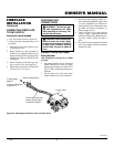
Figure 42 - Attaching Alkaline Battery to
Receiver
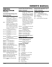
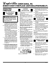
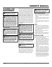
Installing 9-Volt Alkaline Battery
in Hand-Held Remote Control
Unit
1. Remove battery cover on back of re-
mote control unit.
2. Attach terminal wires to a 9-volt alka-
line battery (not included). Place bat-
tery into the battery housing.
3. Replace battery cover onto remote con-
trol unit.
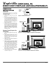
Figure 43 - Installing Alkaline Battery in
Hand-Held Remote Control Unit
Battery
Cover
9-Volt
Alkaline
Battery
Terminal
Wires
Remote
Control Unit
Battery
Housing
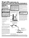
Figure 41 - Control Valve Terminals
To
Optional
Remote
Accessory
Figure 40 - Disconnecting TH to TPTH
Wire
9-Volt Alkaline
Battery
Receiver
Terminal
Wires
Battery Clip
Continued
INSTALLING OPTIONAL
WIRELESS HAND-HELD
REMOTE CONTROL - CGHRC
SERIES/CGHRCT SERIES
NOTICE: Use only alkaline bat-
teries (not included).