


16
104605
DIRECT-VENT FIREPLACE (NATURAL/PROPANE/LP)
CHDV37N/P AND CHDV41N/P
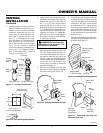
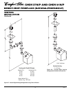
INSTALLING OPTIONAL
BLOWER ACCESSORY
IMPORTANT
: For clarity, gas valve assem-
bly and grate/burner assembly are not shown
in Figures 30 through 33, page 17. They will,
however, be in your fireplace when you are
installing the blower. Also for clarity the
firebox is shown with dotted lines.
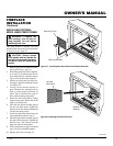
1. Open lower louver panel or remove for
easier access.
2. Place the blower against the lower rear
wall of firebox outer wrapper with the
exhaust port directed upward. Align the
holes in the top mounting tabs of
blower with holes in wall of wrapper
(see Figure 30, page 17). Using the two
screws provided, mount blower and
tighten screws securely.
Note:
For CDA3620T, make sure the
thermal switch is comfortably between
the back of the firebox and the blower
as shown in Figure 31, page 17.
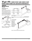
3. Be sure to securely attach all wire ter-
minals to terminals on blower motor
(and thermal switch where applicable)
and that the screw retaining the green
ground wire is tight.
4. Remove screws securing the plate con-
taining the ON/OFF switch to the bot-
tom of the firebox and set aside.
5. Place speed control against back of this
plate and push the plastic control shaft
through opening (see Figure 32, page 17).
6. While supporting speed control, secure con-
trol shaft with lock nut by pushing and turn-
ing lock nut with pliers clockwise until tight
against the plate. Place control knob pro-
vided onto shaft (see Figure 32, page 17).
7. Replace plate containing switches and
tighten screws securely.
NOTICE: If installing blower in an
existing fireplace with gas con-
nections, shut off gas supply and
disconnect heater from gas sup-
ply. Contact a qualified service
person to do this.
CHECK GAS TYPE
Use proper gas type for the fireplace unit
you are installing. If you have conflicting
gas types, do not install fireplace. See re-
tailer where you purchased the fireplace for
proper fireplace according to your gas type.
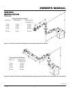
FIREPLACE
INSTALLATION
NOTICE: This heater is intended
for use as supplemental heat. Use
this heater along with your pri-
mary heating system. Do not in-
stall this heater as your primary
heat source. If you have a central
heating system, you may run
system’s circulating blower while
using heater. This will help circu-
late the heat throughout the
house. In the event of a power
outage, you can use this heater
as your primary heat source.
WARNING: A qualified ser-
vice person must install fireplace.
Follow all local codes.
CAUTION: This fireplace cre-
ates warm air currents. These cur-
rents move heat to wall surfaces
next to fireplace. Installing fire-
place next to vinyl or cloth wall
coverings or operating fireplace
where impurities (such as to-
bacco smoke, aromatic candles,
cleaning fluids, oil or kerosene
lamps, etc.) in the air exist, may
discolor walls.
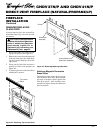
Note:
Your fireplace is designed to be used
in zero clearance installations. Wall or fram-
ing material can be placed directly against
any exterior surface on the rear, sides, or top
of your fireplace, except where standoff
spacers are integrally attached. If standoff
spacers are attached to your fireplace, these
spacers can be placed directly against wall
or framing material. See framing details on
page 4.
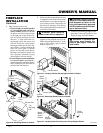
Place the fireplace into position and shim
with noncombustible material if needed.
Nail the side flanges to the framing to secure
the unit in place. There are two floor brack-
ets included with each unit. Use these as an
alternative method of securing the fireplace.
IMPORTANT:
Make sure fireplace is level
before securing. If fireplace is not level it
will not work properly.
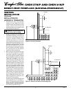
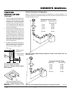
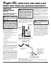
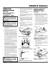
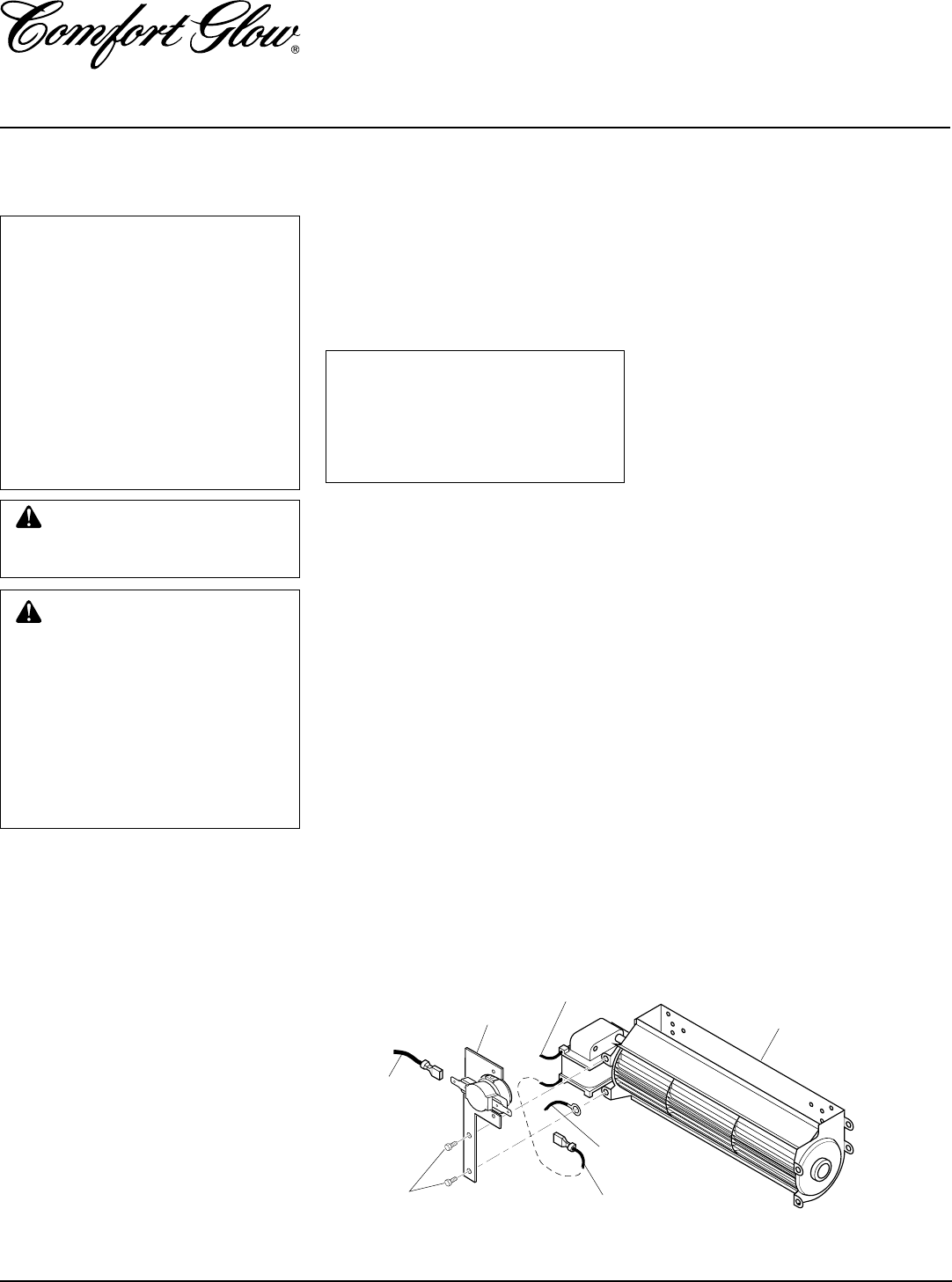
Attaching Thermal Switch to
CDA3620T Thermostatically-
Controlled Blower
When installing the CDA3620T thermo-
statically-controlled blower accessory, you
must first secure the thermal switch to the
blower.
1. Remove the two hex head screws on the
blower assembly as shown in Figure 29.
2. Place the green wire between the bot-
tom hole on the thermal switch bracket
and the bottom hole on the blower as-
sembly. Insert one of the hex screws
into all three pieces and tighten.
3. Insert the top screw through the ther-
mal switch bracket and into the blower
assembly. Tighten screw.
4. Connect the blue wire on the blower
assembly to the right side of the ther-
mal switch.
5. Connect the black wire to the left side
of the thermal switch.
Installing GA3750/CDA3620T
Blowers
Figure 29 - Attaching Thermal Switch to CDA3620T Thermostatically-Controlled
Blower Accessory
Blower Assembly
Blue Wire
Green Wire
Black Wire
White Wire
Hex Head
Screws
Thermal Switch
with Bracket