


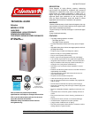

246786-CTG-B-0407
Unitary Products Group 5
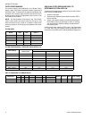
For additional connection diagrams for all UPG equipment refer to “Low Voltage System Wiring” document available online at www.upgnet.com
in the Product Catalog Section.
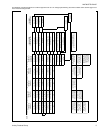
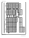
Thermostat Chart - AC
AC10 2 Stage Scroll A/C w/ Variable Speed Furnace - PV8/9; (F,L)*8/9V, (G,L)*8/9V, XYG8V-*, XYF8V-*, XYG9V-*, XYF9V-*
*DN22U00124
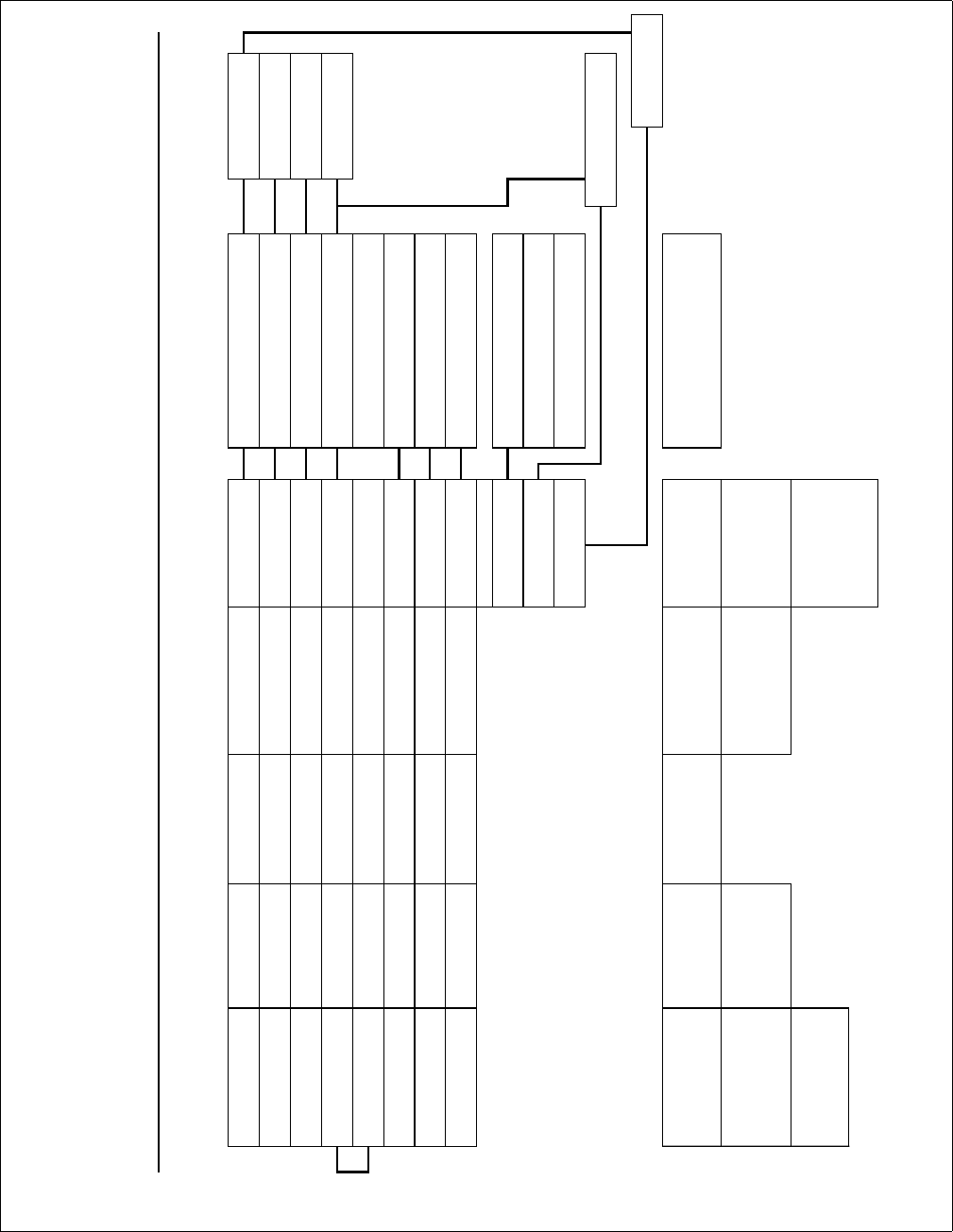
THERMOSTAT
Y
First Stage Cool
R
24-Volt Hot (Heat XFMR)
C
24-Volt Common
THERMOSTAT
Connection of the "C"
Termainal, 24-Volt
Common, is optional
when used with batteries
*PP32U70124
Y
First Stage Cool
Y2
Second Stage Cool
R
24-Volt Hot (Heat XFMR)
C
24-Volt Common
W/W1
Single/First Stage Heat
W2
Second Stage Heat
G
Fan
Thermostat Installer
Setup Number 0170 -
System Type - must be
set to 8 - 2 Heat/2 Cool
Multistage Conventional
G
Fan
G
Fan
E/W1
First Stage Heat
W2
Second Stage Heat
*PP32U72124
RC
24-Volt Hot (Cool XFMR)
E/W1
First Stage Heat
L
Malfunction Light
W2
Second Stage Heat
G
Fan
E/W1
First Stage Heat
Y2
Second Stage Cool
C
24-Volt Common
Y1
First Stage Cool
*DP22U70124
HM
Humidistat
DHM
Dehumidistat
VARIABLE SPEED
FURNACE CONTROL
R
24-Volt Hot
CFM CONTROL
W2
Second Stage Heat
Y1
First Stage Cool
*PP32U71124
THERMOSTAT
24V HUMIDIFIER
(Optional)
(X/L)
Malfunction Light
(O)
Reversing Valve– Energized in Cool
TWO STAGE
AIR CONDITIONING
Comfort Alert
Interface
HUM
Dehumidification - Open on Humidity Rise
C
24-Volt Common
C
24-Volt Common
R
24-Volt Hot
W2
Second Stage Heat
G
Fan
Y2
Second Stage Cool
E/W1
First Stage Heat
RC
24-Volt Hot (Cool XFMR)
Y1
First Stage Cool
R
24-Volt Hot
Y/Y2
Single/Second Stage Cool
Y2
Second Stage Cool
Y
First Stage Cool
Y2
Second Stage Cool
W2
Second Stage Heat
G
Fan
R
24-Volt Hot
W
First Stage Heat
R
24-Volt Hot
*DN22C00124
THERMOSTAT
Y2
Second Stage Cool
Y1
First Stage Cool
C
24-Volt Common
C
24-Volt Common
THERMOSTAT
Thermostat Installer Setup
Number 15 - Compressor
Protection - must be set to 5
( ) CONVENIENCE TERMINAL
NO FUNCTION IN THIS APPLICATION.
E2/P Switch must be in
the E2 position and the
Humidistat Jumper on
CFM Control must be
in the 'YES' position
for Dehumidification
Step 1 of Thermostat User
Configuration Menu
must be set to MS 2
Connection of the "C"
Termainal, 24-Volt Common,
is optional
when used with batteries
Step 16 of Thermostat
User Configuration Menu
must be set to ON to use
Comfort Alert Features
Thermostat Installer Setup
Number 1 - System Type -
must be set to 6 - 2
Heat/2 Cool Conventional
Connection of the "C" Termainal,
24-Volt
Common, is optional
when used with batteries
Connection of the "C"
Termainal, 24-Volt
Common, is optional
when used with batteries
Step 1 of Thermostat User
Configuration Menu must be
set to MLTI STG