8
UVDR Series Unvented Gas Fireplaces
20007469
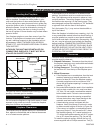
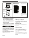
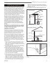
Back Firebrick
T230
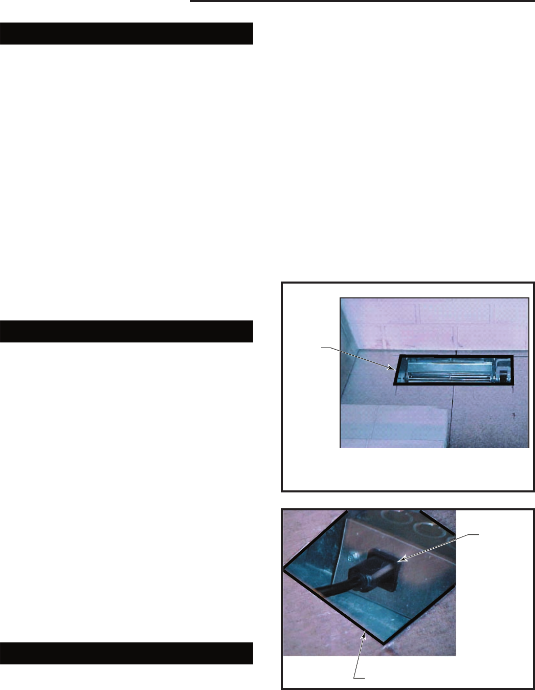
blower access
2/04
Blower
Access
Cutout
inHearth
Pan
NOTE: Hearth brick and/or hearth cover is removed as
shown to gain access for blower and junction box instal-
lation.
T230
Fig. 10 Blower access.
T231
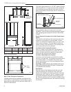
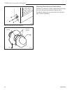
junctin box cutout
2/04
Receptacle
Outlet in Juc-
tion Box
Junction Box Cutout in Hearth
Pan of Firebox
T231
Fig. 11 Route powercord under the hearth pan and plug into
the receptacle outlet.
Blower Installation
BEFORE YOU BEGIN...A FEW BASIC RULES
1. Check to ensure that electrical service has been
provided to the junction box located in the bottom
chamber of the firebox.
2. Check local building codes before installation of the
firebox and the blower kit.
3. All wiring must be installed and/or inspected as
necessary to comply with the local authority having
jurisdiction.
4. The circuit breaker controlling the power supply to
the pre-wired junction box in the appliance must be
in the “OFF” position before beginning installation of
the blower.
5. The appliance, when installed, must be electrically
grounded in accordance with local codes or - in the
absence of local codes - with the National Electri-
cal Code, ANSI/NFPA 70 or the Canadian Electrical
Code, CSA C22.1.
Read all the installation instructions for the appli-
cable appliance before beginning the installation of
the blower.
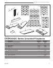
UVDR36C Blower Installation
Step 1: Carefully unpack the blower assembly and
familiarize yourself with the parts. Care should be taken
not to damage the fan blades or housing.
Step 2: The SCVS - Variable Speed Control Kit (or
standard wall switch) should be installed before the
blower assembly installation. Please refer to instruc-
tions found in the SCVS Kit.
Step 3: Remove the bottom brick from the fireplace
and carefully place it to the side to prevent damage.
Use a flat blade screwdriver to gently lift up the front
edge of the brick, then pull forward to remove.
Step 4: Locate the blower access cutout found at the
rear of the hearth pan. Next, remove tape backing from
tape on blower housing. Center the blower assembly in
the access cutout area with the blower outlet duct point-
ing upward, then press firmly to attach foam tape to the
back and bottom of the fireplace. (Fig. 10)
Step 5: Locate the junction box cutout found on the
right side of the hearth pan. Route the powercord under
the hearth pan and plug it into the receptacle outlet
found in the junction box. (Fig. 11)
Step 6: Turn power back on and test blower operation.
Step 7: Replace the bottom brick in the fireplace.
UVDR42C Blower Installation
Step 1: Carefully unpack the blower assembly and
familiarize yourself with the parts. Care should be taken
not to damage the fan blades or housing.
Step 2: The SCVS - Variable Speed Control Kit (or
standard wall switch) should be installed before the
blower assembly installation. Please refer to instruc-
tions found in the SCVS Kit.
Step 3: Remove the metal hearth cover and the bot-
tom two right brick panels from the fireplace and care-
fully place them to the side to prevent damage.
Step 4: Locate the blower access cutout found at the
rear of the hearth pan. Next, remove tape backing from
tape on blower housing. Center the blower assembly in
the access cutout area with the blower outlet duct point-
ing upward, then press firmly to attach foam tape to the
back and bottom of the fireplace. (Fig. 10)
Step 5: Locate the junction box cutout found on the
right side of the hearth pan. Route the powercord under
the hearth pan and plug it into the receptacle outlet
found in the junction box. (Fig. 11)
Step 6: Turn power back on and test blower operation.
Step 7: Replace the metal hearth cover and the bottom
two center panels in the fireplace.