


5
UVDR Series Unvented Gas Fireplaces
20007469
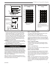
screws are located across the top of the fireplace
opening approximately 5” to the right and left from
center. Two (2) screws are located 4” down from
the top on each side of the fireplace opening. Place
the canopy, making sure the 1/4” hex head screws
across the top of the opening align with the clear-
ance holes in the canopy. Secure with the four (4)
previously removed screws.
WARNING: The firebox canopy must not be modified
or replaced with a canopy that may be provided with
the unvented decorative room heater.
4. Floor Clearances: No clearance is required if the
appliance is installed per these instructions.
Installing the Firebox
This list of specific instructions will help you make cer-
tain that every installation operation is done correctly.
Complete the installation steps in the sequence shown.
LOCAL BUILDING CODES SHOULD BE CONSULTED
IN ALL CASES AS TO THE PARTICULAR REQUIRE
-
MENTS CONCERNING THE INSTALLATION OF FAC-
TORY BUILT FIREPLACES.
Select the location for the fireplace by taking into con
-
sideration the factors previously outlined in the Locating
the Fireplace section of the manual.
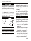
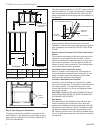
Step 1: Framing the Firebox
The width of the framed opening must be 39” for 36”
models or 45¹⁄₄" for 42" models. (Fig. 4)
The entire fireplace can be elevated above the floor
to achieve a raised hearth effect. This can be done by
adding a small platform to achieve the desired height.
NOTE: Refer to Pre-wiring the Junction Box and Electri-
cal Service on Page 7.
Step 2: Install the Firebox
Install the firebox into the framed opening by setting
it directly in front of the opening and sliding it into the
proper position.
Step 3: Level the Firebox
Check the level of the firebox on the top edge of the fire-
place face. Shim if necessary.
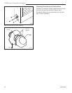
Step 4: Secure the Firebox
Four (4) nailing flanges are supplied with the fireplace
(found on the fireplace hearth). To level the box and
secure it firmly in place, remove the nailing flanges from
the hearth and install at the sides of the fireplace as
shown in Figure 5.
NOTE: The nailing flanges have two (2) sets of holes
to allow for adjustment for 1/2” or 5/8” offset of the face
of the unit. When installing the nailing flanges, choose
the set of holes on the nailing flange that fit with your
application.
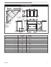
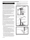
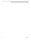
42"
5" Min.
9"
Min.
24"
Min.
10"
FP604a
clearances
2/04
6"
16"
Min.
Combustible Per-
pendicular Wall
3a
Noncombustible
Material
Fireplace
Opening
FP604b
Clearances
without Canopy
3b
3c
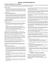
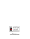
Clearance* from Top of Fireplace Opening (“)
Mantel (Combustible)
Projections (“)
Clearance to Combustible
Mantel Projections with 4”
Canopy
T225
Fig. 3 Clearances to combustibles.
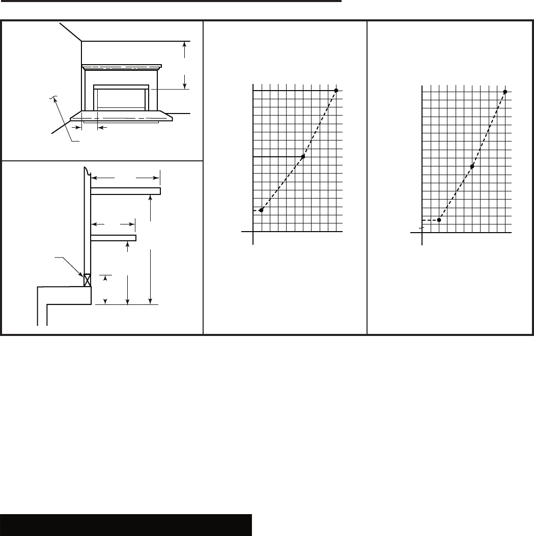
*Combustible Projections
above the fireplace must be
within the area described by the
dashed line.
8
10
12
14
16
18
20
22
24
2 4
6 8
10
8
10
12
14
16
18
20
22
2 4
6 8
10
6
T225
mantel clearance
2/04
Clearance to Combustible
Mantel Projections without
Canopy
3d