


7
UVDR Series Unvented Gas Fireplaces
20007469
FP568
UVBR/CN
7/01
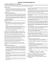
Finishing Material
Stud
Insulation
Noncombustible Material
Caulking or Sealant
Noncombustible
Insulation
Stand-
off
Finishing Material
Caulking or Sealant
Top View
Side View
FP568
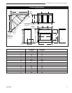
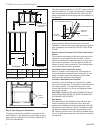
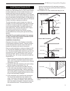
Fig. 7 Sealing spaces between fireplace and finishing materi-
als.
Finishing the Fireplace
There are a wide variety of finishing materials avail-
able for your fireplace from formal wall treatments with
marble and mantels to rustic wood paneling, stone or
brick.
IT IS IMPORTANT THAT THE BLACK FACE OF THE
FIREPLACE NOT BE COVERED WITH ANY TYPE OF
COMBUSTIBLE MATERIAL.
Noncombustible facing materials such as marble, brick
or ceramic tile may overlap the black face of the fire
-
place up to the opening on either side of the fireplace.
Seal all joints between the black fireplace face and the
wall covering with a heat-resistant material such as rock
wool insulation or mortar. Be sure to use high tempera-
ture adhesive or mortar when anchoring brick, stone or
tile to the face of the fireplace. Check to see whether
man-made brick and stone are made of noncombustible
materials before using them on the face of the fireplace.
Some of these products contain combustible materials.
Combustible wall coverings such as paneling or wall-
board may not overlap the black face of the fireplace.
The space between the wall covering and the fireplace
should be sealed with a heat-resistant material such as
rock wool insulation or mortar.
NOTE: An “L” shaped steel lintel must be installed
across the top of the firebox opening where facing
materials such as brick or stone are used on the face
of the firebox. It acts as a support/firestop. It should be
attached to the face of the fireplace with screws and
sealed to the fireplace with a heat-resistant sealer.
WARNING: The firebox screens must be in place be
-
fore operating the fireplace.
WARNING: These vent free fireplaces are not to be
used with glass doors.
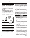
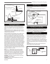
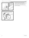
Hearth Extension
A hearth extension may be used but is not required for
these fireboxes.
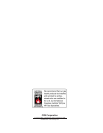
A raised hearth extension may be used as shown in
Figure 8.
T238
Hearth Extension
2/26/04 djt
1/2"
Hearth
Extension
Hearth Brick
Surround
Combustibles Al
-
lowed
(no carpet or vinyl)
Combustible
Plateform
T238
Fig. 8 A raised hearth extension.
Seal with Noncom-
bustible Material
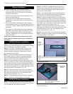
Pre-Wiring of Junction Box
Wiring should be connected at the junction box located
on the right side of the firebox prior to the installation of
the blower kit. A standard wall box should be used to
contain the SCVS - Variable Speed Control Kit.
Electrical Services
If an electrical supply of 120V is being roughed in to the
fireplace junction box to provide for future installation of
optional blower kit, the wiring should be connected to
the junction box located on the right side of the firebox.
NOTE: All electric connections are to be made in ac-
cordance with CSA Standard C22.1-Canadian Electrical
Code part 1 or with the National Electrical Code, ANSI/
NFPA 70 (latest edition) and/or in accordance with local
codes.
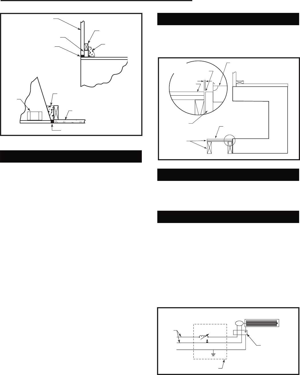
CAUTION: Should this blower require servicing, the
power supply must be disconnected.
M
Black
White
G
T229
Blower
wiring diagram
2/11/04 djt
Firebox Acces-
sory Junction
Box
Speed Control
Switch
120
Volt
Wall Electrical Box
T229
Fig. 9 Blower wiring diagram.