


6
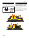
Gas Fireplace Insert
10002964
Combustion Air
It is very important that an adequate air supply is
available when the unit is being operated. Since most
homes of today are tightly sealed and insulated, addi-
tional make-up air is usually necessary.
This fireplace has been designed to operate by drawing
air in from the front and outer perimeters of the fire-
place. The air provides combustion air ensuring a clean
burning flame, dilution air for proper venting, as well
as the air which the fan circulates over the firebox/heat
exchanger system.
NOTE: Insulating around the fireplace will result in
overheating and possible malfunctioning of the circulat-
ing fan.
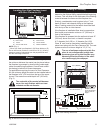
Zero Clearance Applications
An alternate air supply is recommended
with this component.
For installation other than in existing woodburning fire-
places such as new construction or renovation projects,
a Zero Clearance Kit must be used. The kit enables
these inserts to be installed in combustible environ-
ments. Whenever using a Zero Clearance Kit, consid-
eration must be given to the dimensions of the Zero
Clearance Kit and the requirements of the Air Kit when
planning out the installation.
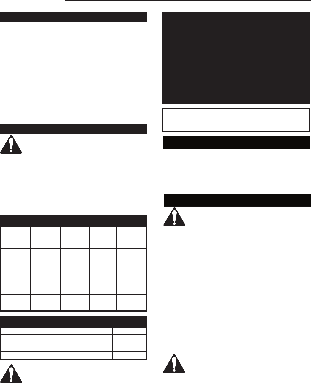
Gas Specifications
Max. Min.
Fuel Gas Input Input
Model Type Control BTU/hr BTU/hr
A125RN Natural Millivolt 20,000 14,000
Hi/Lo
A125RP Propane Millivolt 20,000 15,000
Hi/Lo
A132RN Natural Millivolt 30,000 21,000
Hi/Lo
A132RP Propane Millivolt 30,000 22,500
Hi/Lo
Natural LP
Minimum Inlet Pressure 5.5"
W.C. 11.0" W.C.
Maximum Inlet Pressure 14.0"
W.C. 14.0" W.C.
Manifold Pressure 3.5"
W.C. 10.0" W.C.
Gas Inlet & Manifold Pressures
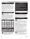
Do not use this appliance if any part of it
has been under water. Immediately call a
qualified service technician to inspect the
unit and replace any part of the control
which has been under water.
High Elevations
Input ratings are shown in BTU per hour and are
certified without deration for elevations up to
4,500 feet (1,370m) above sea level.
For elevations above 4,500 feet (1,370m) in USA,
installations must be in accordance with the
current ANSI Z223.1/NFPA 54 and/or local codes
having jurisdiction.
In Canada, please consult provincial and/or local
authorities having jurisdiction for installations at
elevations above 4,500 feet (1,370m).
These gas inserts are approved for installation
in solid fuel burning masonry or zero clearance
fireplaces.
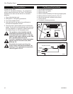
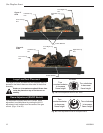
Preparation
Before beginning, remove glass door and logs from
unit. Also check to make sure there is no hidden dam-
age to the unit. Take a minute and plan out the gas,
venting and electrical route. It is best to start with the
gas line first followed by the chimney liner. (Refer to
Page 8)
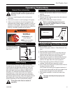
Gas Line Installation
When purging the gas line, the front glass
must be removed.
If gas piping from the source to the heater location
has not been accomplished, install the required pipe.
Consult local plumbing code to assure proper pipe size.
The gas pipeline can be brought in through the rear or
the base of the heater.
NOTE: The gas line connection can be made of either
properly tinned 3/8" copper tubing, 3/8" rigid pipe or
an approved flex connector then reduced to 3/8" to
the heater. Some municipalities have additional local
codes, it is always best to consult your local authority
and the CSA- B149.1 installation code.
U.S. Installations consult the current National Fuel
Gas Code, ANSI Z223.1/NFPA 54.
The gas control inlet is 3/8” N.P.T. therefore the 1/2”
rigid gas line must be reduced to 3/8” N.P.T. A typical
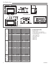
installation layout for rigid pipe is shown in Figure 4.
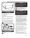
Always check for gas leaks with a mild
soap and water solution. Do not use an
open flame for leak testing.
The gas control is equipped with a captured screw
type pressure test point, therefore it is not necessary to
provide a 1/8" test point up stream of the control.