


10
Gas Fireplace Insert
10002964
Fan Kit Installation
115 Volt, 60 Hz. 56W
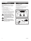
The fan kit includes the following: fan, temperature
sensor, speed control and a 6 ft. cord. The following
explains how to start and set the fan for automatic
operation.
1. Plug in the electrical cord.
2. Start gas fire - see lighting procedures.
3. Turn on fan speed control.
4. Wait until the unit has warmed up sufficiently to
activate the temperature sensor.
5. Once fan starts, adjust speed control to desired fan
speed. The fan will now automatically come on every
time the fireplace is in operation. Should the fan not
be needed simply turn off the speed control.
The appliance, when installed must be
electrically connected and grounded in
accordance with local codes or, in the ab-
sence of local codes, with the current CSA
C22.1 Canadian Electrical Code.
For U.S.A. installations, follow local codes
and the national electrical code, ANSI/
NFPA No. 70.
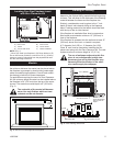
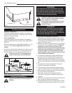
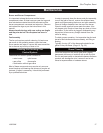
Should this fan require servicing, the
power supply must be disconnected. For
rewiring of any replacement components
refer to Figures 13 & 14.
FP1252
FK24 install
1/03
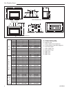
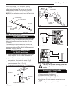
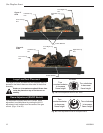
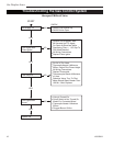
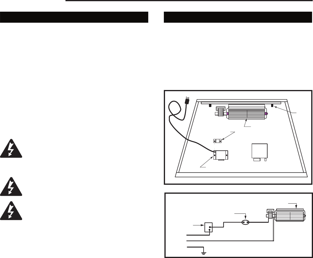
Fan is installed
at the back of
the air intake
box
Stud
Fan Speed Control/Junction Box
Valve
Thermal Sensor is
attached to burner
base
FP1252
Fig. 13 Fan location.
Stud
FP394
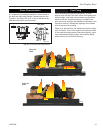
WIRING DIAGRAM
11/20/96
FP394
Black
White
Ground
Speed
Control
Temperature Sensor
Fan
Fig. 14 Wiring diagram RN/RP.
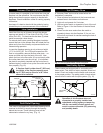
Fan Removal Instructions
1. Turn off gas and electricity.
2. Remove the front glass.
3. Remove the logs.
4. Remove burner assembly and rear log support plate.
5. Remove the fan mounting nuts (2). (Fig. 13)
6. Slip off the electrical connector at the motor.
7. Lift out the fan.
8. To reinstall, reverse procedure.