


22
Gas Fireplace Insert
10002964
1
2
3
4
5
FP1293
HE25FP parts
2/03
FP1293
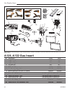
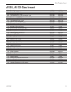
HE25FP Replacement Parts
CFM Corporation reserves the right to make changes in design,
materials, specifications, prices and discontinue colors and products
at any time, without notice.
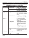
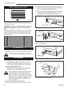
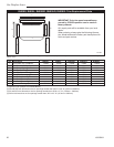
IMPORTANT: Only trim panel assemblies approved
by CFM Corporation can be used on these prod-
ucts.
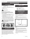
ALL repair parts will be available from your local dealer.
When ordering, always give the following information:
Model and serial number, part description with finish
and part number.
Key Description HE25FP
1 Trim Window Top/Bottom 55098
2 Trim Bottom Channel 55079
3 Top Louvre Assembly 54603
4 Bottom Louvre Assembly 54604
5 Hinge 52356
6 Fasteners Package (Not Shown) 57916
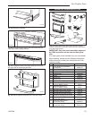
A3 HE25BTKP
For use with A125
HE25BTKP Bay window kit with polished brass trim
Do not remove existing glass with frame.
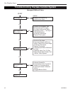
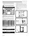
Trim Assembly
1. Reposition controls.
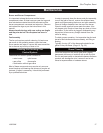
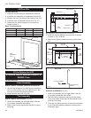
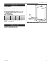
a. Remove the fan speed control box. (Fig. 29)
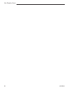
b. Attach the fan speed control box to the bracket
(Fig. 30) and install the bracket into the cabinet.
Only for RN/RP VALVE units:
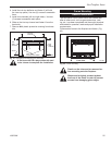
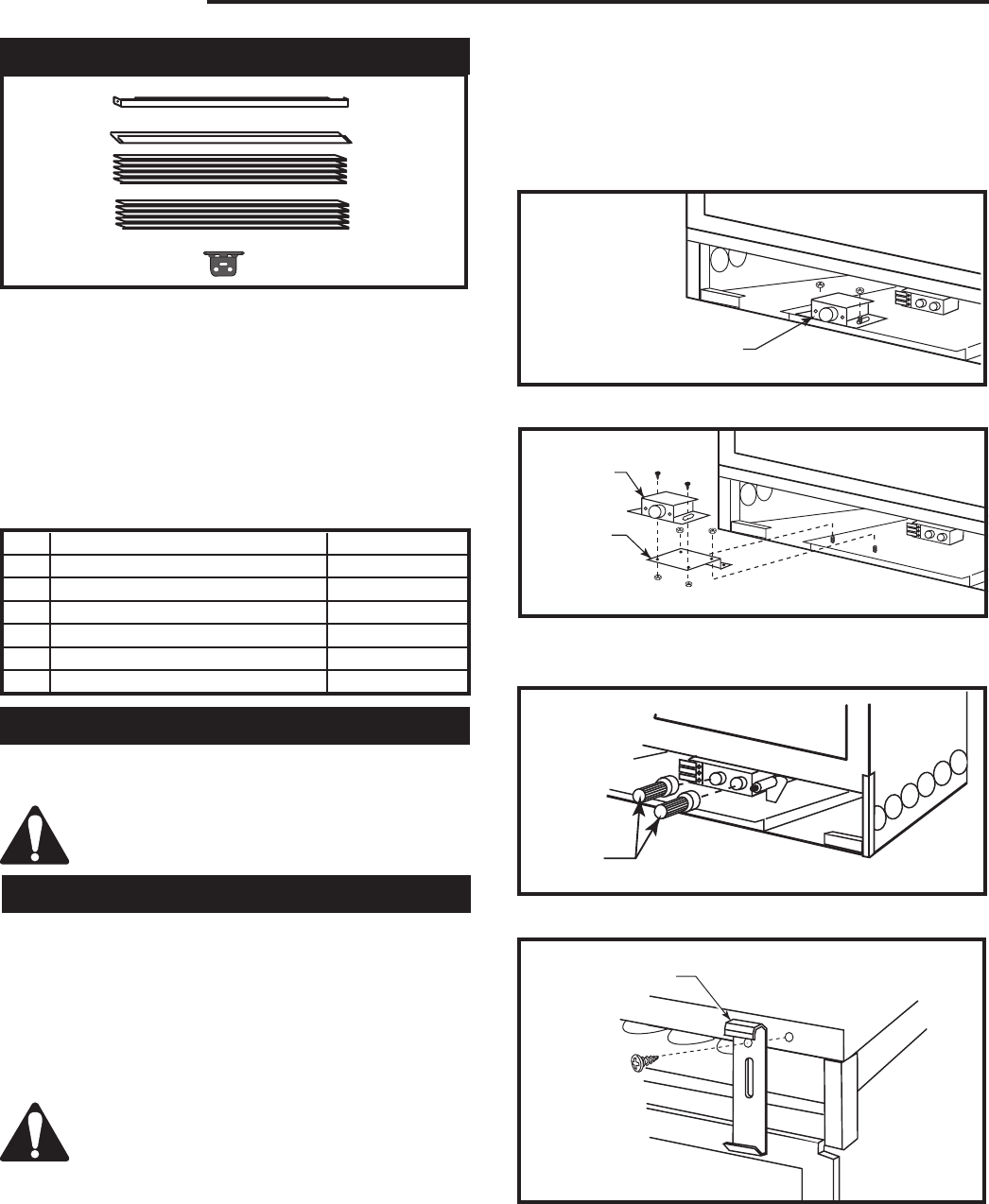
c. Install the control knob extensions onto the ap
-
propriate control valve knobs. (Fig. 31)
On units fitted with a Honeywell brand control
valve the location of the control knobs and
the ignitor button may vary slightly from those
shown in Figure 31. The Honeywell extension
pieces are visually different in design and are
not interchangeable with the RN/RP knobs
shown in Figure 31.
2. Install the hanging brackets. (Fig. 32)
3. Install bracket on each side of the cabinet. Fig. 33)
4. Install the ceramic piece inside the bay window.
5. Install the bay window by hanging it onto the lower
tabs of the hanging brackets. (Fig. 34)
6. Install top louvre by engaging the oblong holes with
the upper tabs of the hanging brackets. (Fig. 35)
7. Install brass trim to the steel frame. (Fig. 36)
KT207
Bay Front
attach fan control box
HEDV30/HEDV32
3/19/01 djt
Fan Control
Box
Extension
Bracket
KT207
Fig. 30 Attach the control box to the bracket and install
bracket into the cabinet.
KT204
Bay front
knob ext
3/19/01 djt
Extension
Knobs
KT204a
Fig. 31 Install the knob extensions. (RN/RP models Only)
KT205
Bay Front
remove fan control box
3/19/01 djt
Fan Control Box
KT205
Fig. 29 Remove fan control box.
KT203
Bay Front
Hanging bracket HEDV30
3/19/01 djt
Hanging Bracket
KT209b
Fig. 32 Hanging bracket alignment.