


13
Dutchwest
7001135
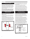
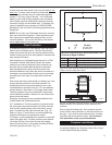
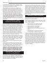
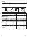
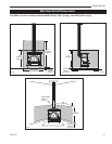
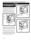
1 Shielding for a top exit stove must include a shield insert to protect the area behind the flue collar.
2 Chimney connector heat shields must extend exactly 24” (610 mm) above the flue collar of the stove.
3 All installations venting straight up to a factory built chimney require a 24” (610 mm) diameter or square ceiling heat shield. The ceiling
heat shield should be 24 gauge sheet metal or equivalent mounted on 1” (25 mm) non-combustible spacers 1” (25 mm) below ceiling.
4 Chimney connector heat shields must extend to within 1” (25 mm) or less of the ceiling heat shield for installations venting straight up to
a factory-built chimney. In top exit installations using an elbow to vent to the rear, the chimney connector must be shielded over the entire
vertical length.
5 If a single-wall oval-to-round adaptor is used, a shield must be used to protect combustibles to the rear of the adaptor.
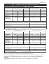
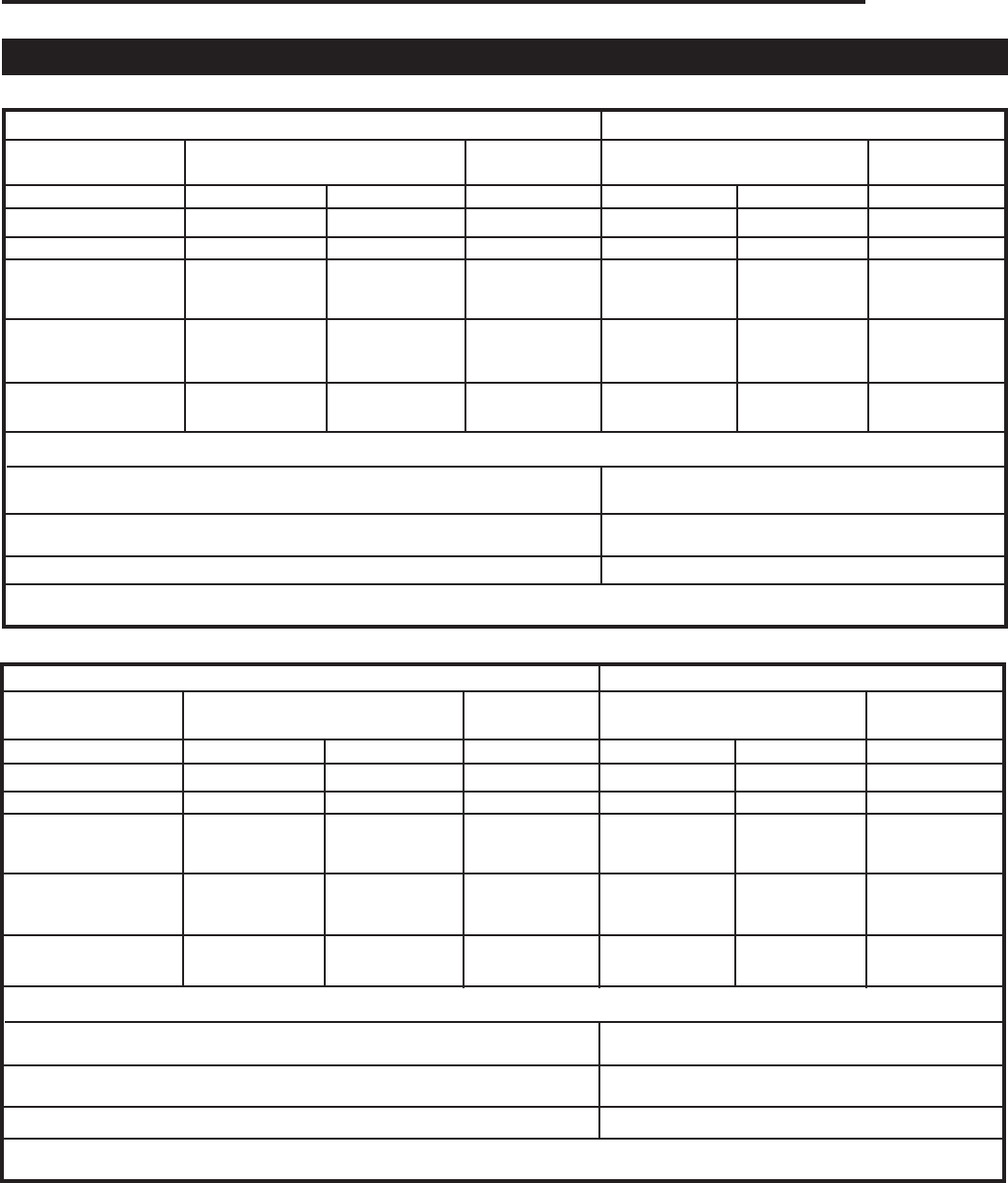
Stove and Chimney Connector Clearance Charts
Stove Clearance Side Rear Corner Side Rear Corner
No heat shields [A] 22” (560 mm) [B] 24” (610 mm) [C] 18” (460 mm) [D] 12” (300 mm) [E] 14” (360 mm) [F] 10” (250 mm)
Rear exit, rear h.s. [G] 22” (560 mm) [H] 14” (360 mm) N/A [I] 12” (300 mm) [J] 12” (300 mm) N/A
Top exit
1
, rear h.s.
Single-wall connector [K] 22” (560 mm) [L] 24” (610 mm) [M] 18” (460 mm) [N] 12” (300 mm) [O] 14” (360 mm) [P] 10” (250 mm)
No connector h.s.
Top exit
1,2
, rear h.s.
Single-wall connec- [K] 22” (560 mm) [L] 14” (360 mm) [M] 15” (380 mm) [N] 12”(300 mm) [O] 12” (360 mm) [P] 8” (200 mm)
tor with connector h.s.
Top exit
1
, rear h.s.
Double-wall connector [K] 22” (560 mm) [L] 19” (480 mm) [M] 15” (380 mm) [N] 12” (300 mm [O] 11” (280 mm) [P] 8” (200 mm)
Chimney Connector Clearance:
Single-wall connector 19” 480 mm) 9” (230 mm)
No connector h.s
Single-wall
2
connector 9” (360 mm) 7” (180 mm)
With connector h.s.
Double-wall connector 14” (360 mm) 6” (150 mm)
Front Clearance to Combustibles: 48” (1220 mm) (All Installations)
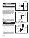
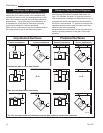
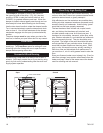
Model 2460 Small Convection, and Model 2461 Large Convection:
UNPROTECTED SURFACES PROTECTED SURFACES
Corner Corner
Parallel Installations Installations Parallel Installations Installations
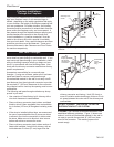
Model 2462 Extra-Large Convection:
Stove Clearance Side Rear Corner Side Rear Corner
No heat shields [A] 20” (510 mm) [B] 23” (580 mm) [C] 18” (460 mm) [D] 18” (460 mm) [E] 18” (460 mm) [F] 17” (430 mm)
Rear exit, rear h.s. [G] 20” (510 mm) [H] 18” (460 mm) N/A [I] 18” (460 mm) [J] 12” (300 mm) N/A
Top exit
1
, rear h.s.
Single-wall connector [K] 20” (510 mm) [L] 23” (580 mm) [M] 18” (460 mm) [N] 18” (460 mm) [O] 18” (460 mm) [P] 17” (430 mm)
No connector h.s.
Top exit
1,2
, rear h.s.
Single-wall connec- [K] 20” (510 mm) [L] 18” (460 mm) [M] 17” (430 mm) [N] 18” (460 mm) [O] 12” (300 mm) [P] 15” (380 mm)
tor with connector h.s.
Top exit
1
, rear h.s.
Double-wall connector [K] 20” (510 mm) [L] 14” (360 mm) [M] 16” (410 mm) [N] 18” (460 mm) [O] 12” (300 mm) [P] 15” (380 mm)
Chimney Connector Clearance:
Single-wall connector 18” (460 mm) 13” (330 mm)
No connector h.s
Single-wall
2
connector 13” (330 mm) 7” (180 mm)
3,4
With connector h.s.
Double-wall connector 8” (200 mm) 6” (150 mm)
Front Clearance to Combustibles: 48” (1220 mm) (All Installations)
UNPROTECTED SURFACES PROTECTED SURFACES
Corner Corner
Parallel Installations Installations Parallel Installations Installations