


12
Dutchwest
7001135
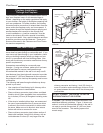
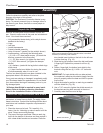
Designing a Safe Installation
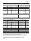
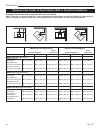
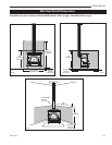
The section that follows contains charts with the infor-
mation that you’ll need to make your installation safe.
Included are a chart to tell you exactly where to cut the
hole in the ceiling so that the stove will meet clearance
requirements, a chart that gives stove clearances for
all installations, and a chart to illustrate the required
sizes of wall shields for various installations.
Refer to these charts as you plan the installation and do
not compromise on any of the dimensions listed.
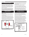
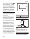
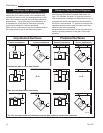
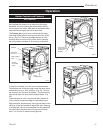
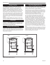
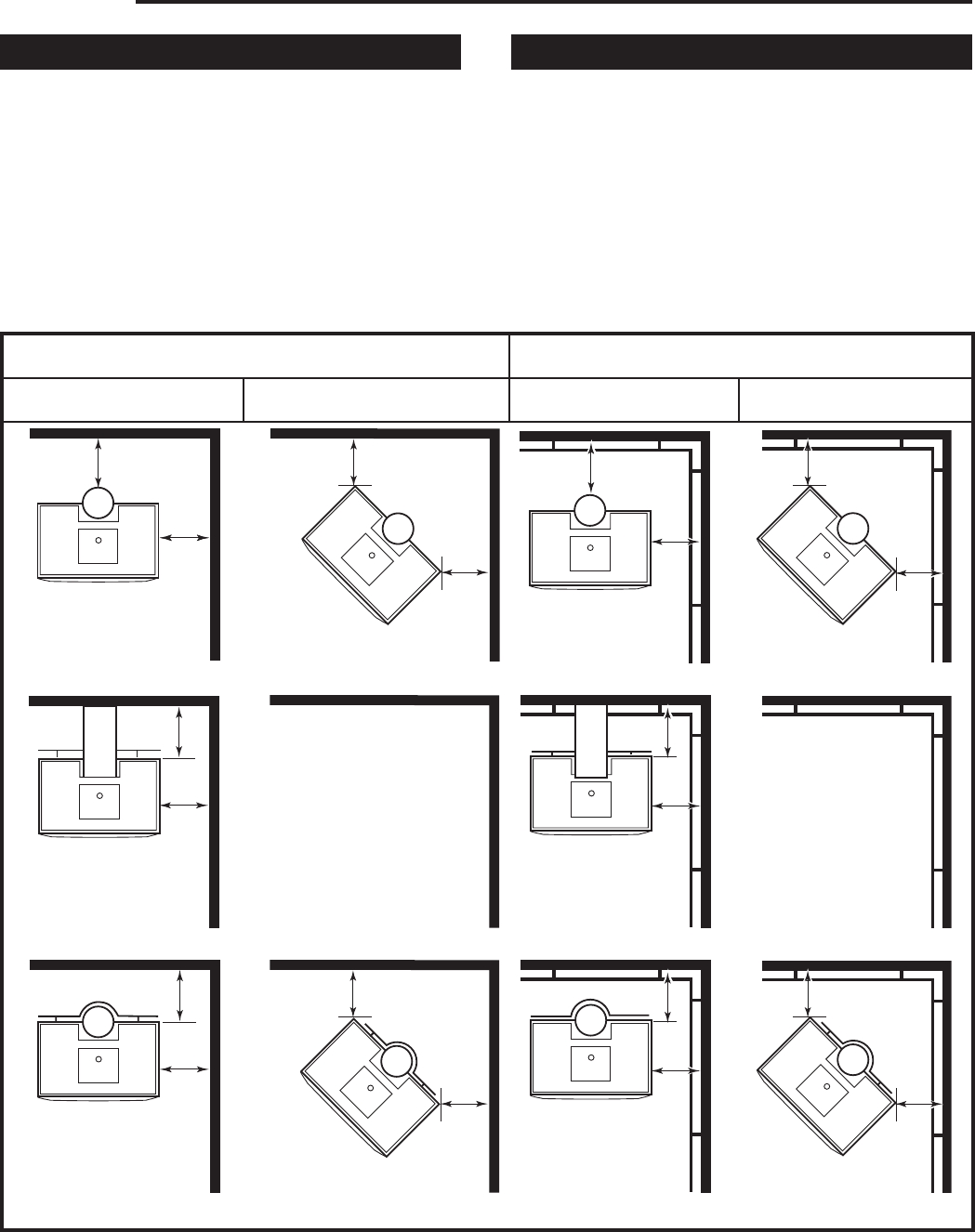
Clearance Chart Reference Diagrams
Refer to the diagrams below when using the Stove
and Chimney Connector Clearance Chart which fol-
lows. For example, the letter “A” gives the minimum
side clearance for installations in which the stove is not
equipped with a rear heat shield and the wall beside
the stove is not protected. “D” gives the minimum side
clearance when the stove does not have a rear heat
shield, but the wall is protected.
Measure clearance distances from the top plate of the
stove or chimney connector to the wall, not the wall
protector.
ST255a
exit diagram
6/30/00 djt
Unprotected Surfaces Protected Surfaces
Parallel Installations Corner Installations Parallel Installations Corner Installations
Installations with no stove heat shields
Rear exit, rear heat shield installations
Top exit, rear heat shield and chimney connector heat shields or double wall connector
A
B
C
C
H
G N / A
E
D
J
I
N / A
F
F
L
K
M
M
O
N
P
P
ST255a