


Clarke
®
Operator's Manual - Encore S30/L30 Page -15-
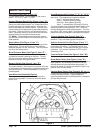
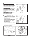
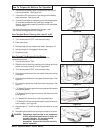
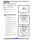
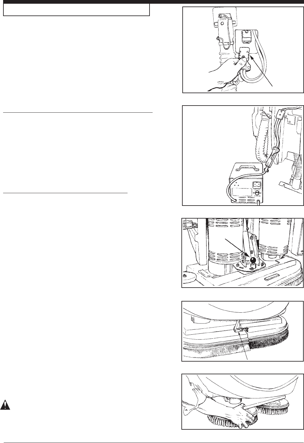
4. Disconnect the battery pack connector from the control
housing connector. See figure 14A.
5. Connect the DC connector on the charger to the battery
pack connector. See figure 14B.
6. Connect the charger to a properly grounded single phase
(3-wire) wall receptacle having the input voltage, fre-
quency, and ampere capacity specified on the nameplate
of the charger.
For more information on the use of the charger, read
the instructions supplied with the charger.
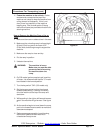
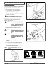
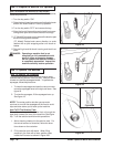
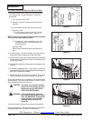
How To Adjust Brush Cleaning Path from 24" to 26"
1. Insure brush head is in up position.
2. Turn the key switch "OFF" and remove the key.
3. Open front cover.
4. Raise plunger pin and rotate brush head. See figure 15.
5. Insure plunger pin is engaged in brush plate.
6. Close front cover.
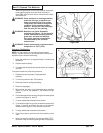
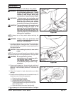
How To Install The Brushes Or Pad Drivers
To install the brushes or pad drivers on the machine,
follow this procedure:
1. Turn the key switch "ON".
2. Raise the brush head by pressing and holding the brush
switch until brush head is in its full up position.
3. Turn the key switch "OFF" and remove the key.
4. Go to the front of the machine and unlatch front cover, swing
cover open.
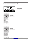
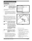
5. Unlatch right and left brush housings and remove them. See
figure 16.
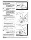
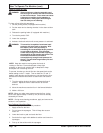
6. Put a brush or pad driver under the brush motor plate. See
figure 17.
7. ("L" Model) Align the lugs on the motor gimbal with the slots
in the brush gimbal.
("S" Model) Align the lugs on the motor with the slots on the
brush gimbal.
8. ("L" Model) Pull the brush up until the gimbal locks.
("S" Model) Pull the brush up and rotate counter direction to
scrub rotation, until lugs lock.
9. Repeat steps 6, 7, and 8 to install the second brush or pad
driver.
10. Reinstall right and left brush housings and latch front cover.
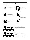
DANGER: Operating a machine that is not completely
or fully assembled could result in injury or
property damage. Do not operate this
machine unless it is completely
assembled. Inspect the machine carefully
before operation.
How To Prepare the Machine For Operation
Figure 14A
Figure 14B
Figure 15
Figure 16
Figure 17