


Page 18 Clarke
®
BEXT
®
-100, 100H 150H, 300HV Operator's Manual
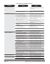
1
2
3
VAC
PUMP
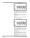
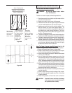
VAC ( 1 ) & PUMP ( 2 ) SWITCHES: These switches are powered
by cord #1 (4" red band). Switches are on when illuminated.
CARPET / UPHOLSTERY SWITCH ( 3 ): This switch is also
powered by cord #1. The carpet setting (down position) is high
pressure (approximately 300 psi). The upholstery setting (up
position) is low pressure (approximately 75 psi). NOTE: Switch
does not illuminate.
HEAT SWITCH ( 4): Turning on this switch (switch illuminates
when on) turns the heater on.
GREEN CIRCUIT LOCATOR LIGHT ( 5 ): When this light is illumi-
nated, it confirms that the machine is on two separate circuits.
See previous page for additional information on the circuit
locator.
HEAT LIGHT MODE ( 6 ) : The light will only illuminate when the
heater uis heating and will turn off when it reaches operating
temperature.
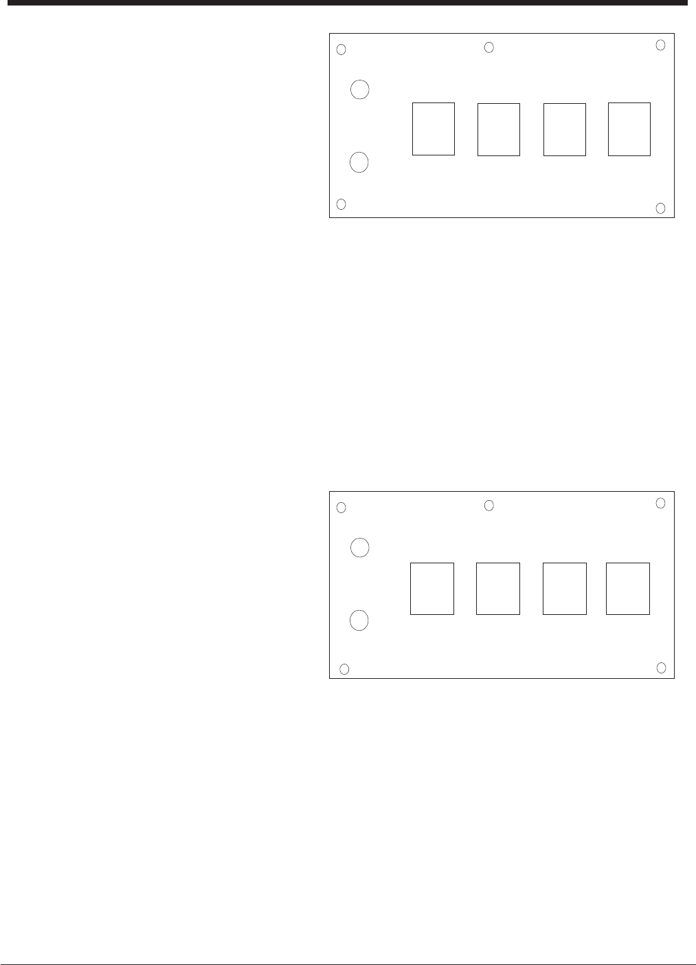
Figure 7
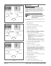
BEXT
®
-300 HV Control Panel
4
HEAT
MODE
LOCATOR
5
6
CARPET
3
4
5
VAC 1 VAC 2
PUMP
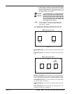
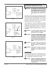
CIRCUIT LOCATOR ( 1 ): When this light is on, it indicates that cord
#2 is on a separate line from cord #1. Cord #2 supplies voltage
to the heater allowing it to heat to the proper temperature range.
HEAT MODE LIGHT ( 2 ): This light will only illuminate when the
heater is heating and will turn off when it reaches operating
temperature.
VACUUM SWITCH ( 3 & 4): Each switch turns on one vac motor.
turn both switches on for maximum lift. The vac switches illumi-
nate when turned on.
PUMP SWITCH ( 5 ): This switch will illuminate when the pump is
on.
HEAT SWITCH ( 6 ) : The heat switch will illuminate when it is
activated and will turn the heater on.
Figure 6
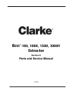
6
HEAT
MODE
LOCATOR
1
2
BEXT
®
-150 H Control Panel
Upholstery