


Page 12 Clarke
®
BEXT
®
-100, 100H 150H, 300HV Operator's Manual
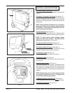
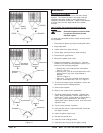
CONTROLS and MACHINE FEATURES
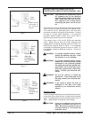
The Vacuum Motor Switches See Figure 1-A
The vacuum motor switches are located on the top of the
machine.
The Switch To Activate The Pump See Figure 1-B
The switch to start/stop the pump motor is on the top of the
machine. Press the lever on the floor tool to start the
solution flow. Release the lever on the floor tool to stop the
solution flow.
NOTE: While the BEXT-150 machine is in operation,
the pump will shut-off automatically when it reaches
full pressure. The pump will automatically turn on
when the pressure decreases.
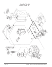
The Float Shut-Off -See Figure 1C
The float shut-off is in the recovery tank. When the liquid
raises the float, the air stops moving through the machine.
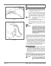
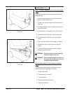
NOTE: To avoid vacuum motor damage, always
inspect the float filter and ball. Verify ball travels
easily prior to use of unit. See Figure 2
The Vacuum Hose Connector See figure 1D
The vacuum hose connector is on the front of the unit.
The Solution Hose Connector See Figure 1E
The solution hose connector is on the lower part of the
extractor, below the vacuum hose connector.
The Recovery Tank See Figure 1F
The recovery tank is in the top of the machine.
The Solution Tank See Figure 1G
The solution tank is in the top of the machine next to the
recovery tank.
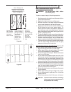
Electric Circuit Locator See Figure 1H
This unique, patented "smart system", operated by a solid
state circuit, will inform the operator when the two cords
are plugged into separate circuits by illuminating the
"Locator" indicator light. This helps prevent tripping circuit
breakers.
NOTE: Ground plug on the cord is required to allow
circuit locator to operate correctly. The system will
not function without proper ground.
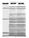
The Machine Power Cord (Red "H") See Figure 1I
This cord powers all machine functions except the heater.
The Heater Power Cord See Figure 1J
This cord powers heater only.
Figure 1
1G
1H
1B
1A
1C
1F
1E
1D
Figure 1
1I
1J
Figure 2