


2-6
Cisco Video Surveillance 3530 IP Camera Installation Guide
OL-28689-01
Chapter 2 Camera Installation
Installing the IP Camera with a Vandal Resistant Enclosure
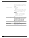
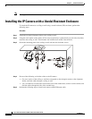
d. Press the Ethernet cable into the routing path at the bottom of the camera so that the cable will not
get in the way when the metal mounting plate is attached.
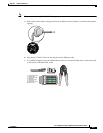
Step 6 (Optional) Perform the following steps to install and connect an external power cable and I/O cables for
external devices:
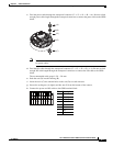
a. Disassemble the components of the waterproof connector into parts (A) ~ (F).
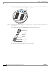
b. Place the screw nut (E) on the power and I/O cable opening.
Sealing Nut (A)
Housing (B)
Seals (C)
Seal (D)
Screw Nut (E)
Hex Nut (F)