


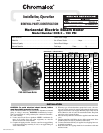
NOTES
1. Motor, Solenoid Valve and Dotted Control Wiring are included if
Motor and Pump package is supplied. Solenoid Valve only is sup-
plied with 99117 Water feed.
2. 1/3 HP Motor is controlled directly without use of Motor Starter.
After proper wiring and piping of boiler system is complete, testing of
controls can start. Before testing controls, it is recommended that all
contactor fusing be removed. This is to prevent possible element fail-
ure under test conditions.
CAUTION: Be sure all electrical connections are tight
before energizing boiler. Reset all manual reset con-
trols by pushing reset buttons on: (1) high limit control
located on top of boiler and (2) McDonnell-Miller locat-
ed on side of boiler.
A. McDONNELL & MILLER LOW WATER CUTOFF CON-
TROL OPERATION AND TESTING
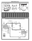
1. Be sure all valves from incoming water supply are fully open. Turn
boiler switch to “ON” position, pump or solenoid valve will ener-
gize, allowing boiler to fill with water. Proper water level is auto-
matically reached with level control supplied. Pump or solenoid
feed will shut off at proper water level. Contactor(s) will energize,
supplying power voltage to elements.
2. Checking operation of pump switch. (Figure 11) With water level
visible in sight glass, partially open drain valve at bottom of boil-
er. If automatic blowdown supplied, push manual blowdown
switch until valve open light is on, hold for few seconds. Water
level will fall, allowing float to trip pump switch to “ON” position.
Close drain valve or release manual blowdown switch. Pump
motor or solenoid valve will energize and water level will resume
to normal level in sight glass.
3. Checking low water cutout switch operation, open drain valve
completely. If automatic blowdown supplied, push in and hold
manual blowdown switch until water level falls enough to trip
cutout switch. Close drain valve or release manual blowdown
switch. If low water cutout is automatic reset, pump or solenoid
will return water level to normal. If low water cutout is manual
reset, then manual reset button on McDonnell & Miller low water
cutoff control must be pushed to complete circuit. Turn off boiler.
Reinstall contactor fuses.
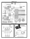
B. ADJUSTING OPERATING PRESSURE CONTROLS
1. Chromalox boilers are supplied with operating and high limit pres-
sure controls. One is used for controlling the operating pressure of
the boiler while the other is used as a high limit control. To deter-
mine the difference in the controls, the high limit has a manual
reset lever on top of the case. Also, there is no differential scale
present.
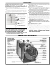
2. On all controls, the pressure adjusting screw on the top of the case
sets the desired pressure. Turning the screw counterclockwise
reduces the pressure setting (see Figure 12). High limit control
should be set at 10 psig above the operating pressure of the boiler.
3. The differential adjusting screw on the operating control is set in
the same manner as the pressure adjusting screw. This scale set-
ting, plus the main scale setting, equals cutout pressure of the oper-
ating control. (Scale A thru F equals 3 psi per letter. L9l B only)
L404A Differential is indicated on Scale Plate.
To check operation of the controls, close steam outlet valve and
adjust operating pressure control to a low pressure setting. Also,
set high limit control at 10 psig above operating pressure control.
Turn on boiler and allow pressure to build up. When pressure
gauge reading approaches set point of pressure control, the switch
will trip and shut off boiler. Turn boiler main switch to “OFF".
To reset pressure control, bleed off enough pressure in the boiler
by opening steam outlet drain, or blowdown valve to allow the
operating control to reset.
4. HIGH LIMlT PRESSURE CONTROL OPERATION. The
high limit is tested in the same manner but with the operating con-
trol set above the pressure setting of the high limit. (Figure 13)
CAUTION: THIS IS FOR TEST PURPOSES ONLY!
When the high limit trips turn off boiler and reset high limit to
proper setting, the manual reset level must be pushed to resume
operation upon startup.
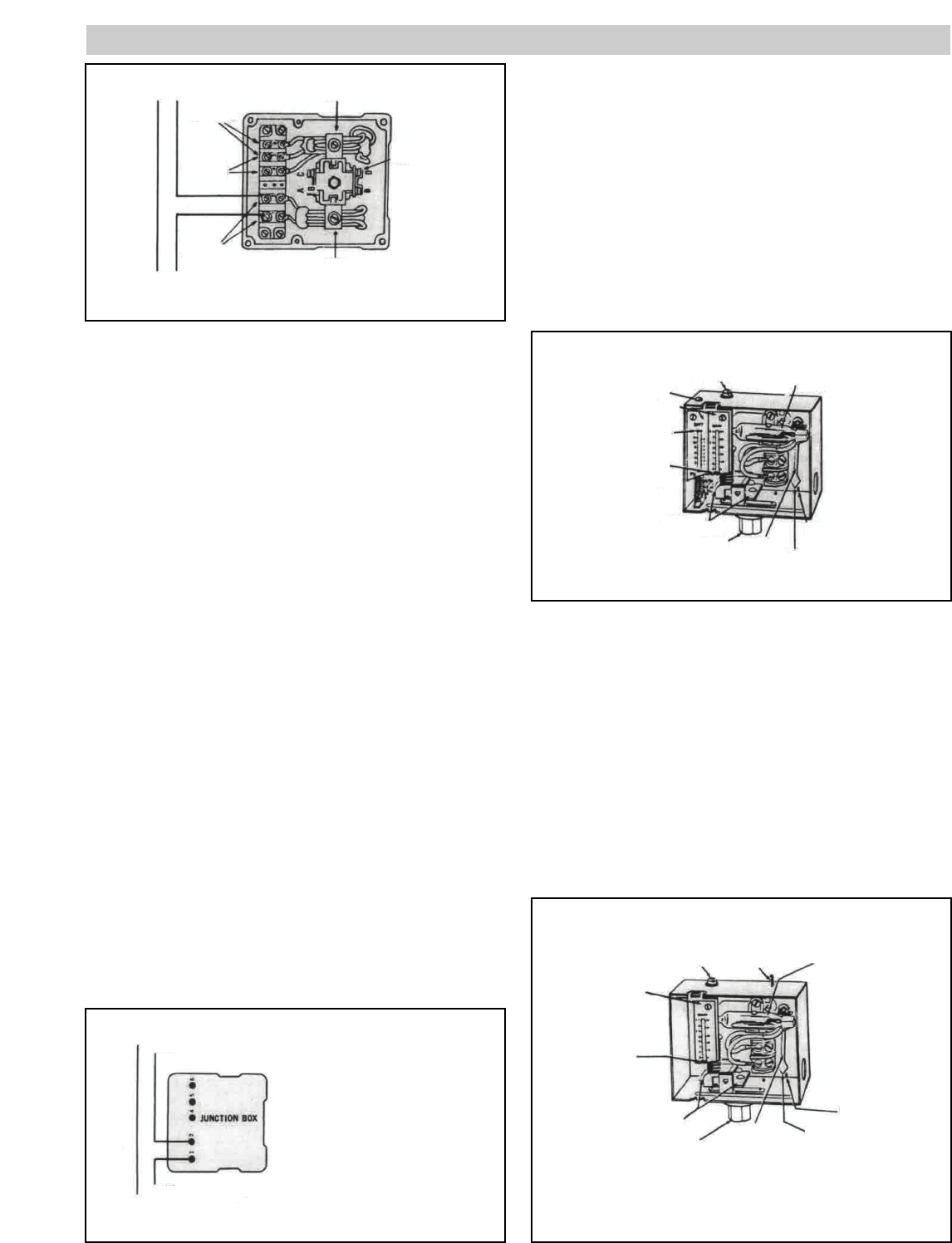
5
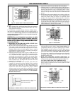
PRE-OPERATION CHECK
Pump
Line
Low Water
Cut-Off
Terminals
Alarm
Circuit
Terminals
Cut-Off and
Alarm Switch
Adjusting
Screws
Pump
Switch
Pump
Circuit
Terminals
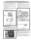
Figure 11 – Automatic Reset Low Water Cutoff Junction Box
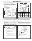
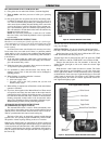
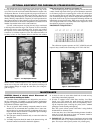
Pump
Line
For pump motors 1/2 h.p. Single Phase
or less, or D.C. 1/4 h.p. or less,
wire as main line switch.
Wiring Diagram – McDonnell & Miller Low Water Cutoff and Pump Control
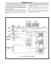
Differential
Adjusting
Screw
Pressure
Adjusting
Screw
Mercury
Switch
Differential
Setting
Indicator
Pressure
Setting
Indicator
Operating Lever
Diaphragm Assembly
Leveling
Indicator
Pointer
Index Mark
Figure 12 – Pressure Control
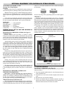
Pressure
Adjusting
Screw
Manual
Reset
Lever
Mercury
Switch
Index
Mark
Pointer
Leveling
Indicator
Diaphragm
Assembly
Operating Lever
Pressure
Setting
Indicator
Scaleplate
Wiring Diagram – McDonnell & Miller Low Water Cutoff and Pump Control