


11
MAINTENANCE
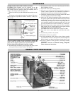
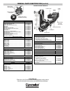
RENEWAL PARTS IDENTIFICATION
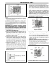
INSTRUCTIONS FOR ELEMENT REPLACEMENT
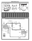
CAUTION: Before installing your new elements, be sure the
McDonnell-Miller low-water cut-off is operating perfectly and the
float chamber and lower equalizer column are completely clear of
sludge or other foreign matter. (See Figure 23)
Failure to do this may cause the immediate burnout of the new ele-
ments.
All elements are thoroughly checked before shipment. The manu-
facturer cannot be responsible for burnouts caused by a faulty low-
water cut-off.
The lower equalizer column can best be examined by breaking the
unions on either side and then visually and manually examining the
piping with your fingers or probes to see if it is clear and clean.
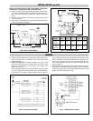
READ COMPLETELY BEFORE STARTING WORK
1. Disconnect boiler from electric power supply at main safety switch
or fuse panel. Then turn boiler switch to “off” position.
2. On automatic feed units, close valve on incoming water line. Drain
boiler completely of water.
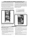
3. Open boiler door to expose heating element.
4. Disconnect wire (electric) leads connecting element to main power
system of boiler. Again note wire connections to facilitate re-
assembly. Proceed to remove (6) 5/16-18 bolts from flange.
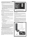
5. Thoroughly clean boiler flange of all foreign material. Be certain
no part of old gasket remains on boiler flange.
6. Apply “Slic-Tite” Gasket Compound (or equal) to both surfaces of
new gasket supplied with replacement element. Proceed to install
element flange assembly with gasket between boiler flange and
clement flange. In doing this, be careful to align flange holes so
wire connection terminals on element assembly are in line with
previously disconnected wire leads to facilitate easy connections.
7. When all (6) flange bolts are tight, connect all wires to terminals.
Make certain wires are clean and bright to assure good electrical
contact and nuts on screws are firmly secured.
CAUTION: Bolts should be lightened 10 a torque of 22 ftlbs.
8. Open water valve so water supply can reach boiler feed mecha-
nism.
9. Put main safety switch to “on” position.
10. Turn boiler switch to “on” position.
11. As boiler automatically refills, observe the new flange assembly
for possible leaks. If water is noticed, the bolts must be retightened.
Before doing this, turn the boiler off at the main fuse safety switch.
12. As boiler is heated to working pressure, check flange assembly
again for leaks.
CAUTION - Avoid use of chemical cleaning compounds.
Follow maintenance instructions.
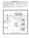
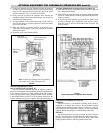
1” Steam Equalizing Pipe
Pump and low water control
Normal Boiler
Water Line
Cut-off Level is
arrow mark
Blowdown
Valve
1” Water equalizing pipe
Figure 23