


3
INSTALLATION (cont’d.)
SPECIAL INSTRUCTIONS FOR CUSTOMERS SUPPLYING
THEIR OWN CONDENSATE OR PUMP SYSTEMS.
1. Check the voltage of the motor before making the wiring connec-
tion. Some Chromalox boilers are supplied with dual voltage sys-
tems. The motor should always match the voltage of the control
circuit.
2. The motor circuit should be wired into the pump control as shown
in wiring diagram.
3. A heavy-duty vacuum breaker is required when condensate system
is used. (part number ES-89369)
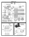
WIRING
1. Wiring to boiler should be as per appropriate wiring diagram sup-
plied with boiler and in accordance with Local and National
Electrical Codes.
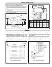
2. SAFETY SWITCHES - Purchaser should use a safety switch
between his main power source and the boiler. The safety switch
should use circuit breakers or fuses and be in accordance with
NEC and local codes.
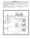
Serious thought should be given to the advisability of using a shunt
trip safety switch of the circuit breaker type as an additional safe-
ty precaution. It is possible to utilize the spare contacts in the low
water cutoff to energize the shunt mechanism on the safety switch.
This is an additional safety feature that prevents a dangerous situ-
ation should a contactor or relay stick. Activation of the shunt trip
device will completely disconnect the boiler from the power sup-
ply. (See Figure 7).
3. Since boiler heating elements are susceptible to lightning damage,
plants not having lightning arresters that have above-ground elec-
trical cable supply sources should install lightning arresters in the
proper size to meet the boiler kw load.
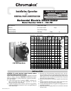
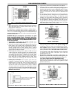
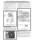
1/2” Water Line
1/2” Solenoid
6-5/8”
1/2” Strainer
3”
7-1/4”
15-1/4” for CHS-150
16-3/8” for CHS-180 to 300
1” Discharge
to Boiler
4-1/4”
5-7/8”
Width – 6-1/2
Figure 4 – Motor and Pump Assembly
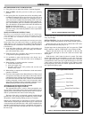
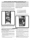
To Aux.
L.W. C.O.
Hi-Limit
Pressuretrol
Operating
Pressuretrols
To L2 on
Terminal Strip
Common
*Standard on CHS-150 to CHS-300 units in lieu of step
sequencer and operating pressuretrol shown in Figure 8
Figure 6 – Pressuretrol Control System*
Shunt Trip Device
(Supplied by Others)
Supply
Voltage
To Field
Wiring
Input
Terminal
To
L2
To Main
Switch
To Motor Starter
L.W.C.O. &
Pump Control
To Aux.
L.W.C.O.
Figure 7 – Safety Switch (Field Installed)
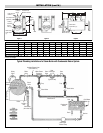
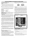
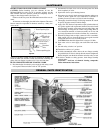
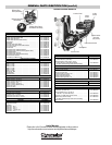
“W” Dimension – Overall Width
Strainers
H
1/2”
Water
Line
L
1” Outlet
to Boiler
Motor and
Pump
1” Drain
1” Vent
1” Condensate
Return
Figure 5 – Condensate Return System
Model Max. Tank Cap.
Number PSI (Gal.) L H W
CHS-150
thru 125 33 33-1/4 41-1/2 21
CHS-300
CHS-360
thru 150 40 40 41-1/2 21
CHS-420