


CALIBRATION
THERMOSTAT SUB ASSEMBLY REPLACEMENT
DANGER: Calibration will involve exposure of inter-
nal control terminals to ambient conditions during
some part of the recalibration procedure.
Combustible materials which cause hazardous
conditions must not be present during recalibra-
tion process — otherwise explosion may result.
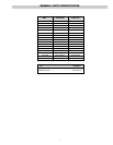
1. Heat water bath or the equipment in which the control is
installed (tank, die, platen or machine) to the selected calibra-
tion temperature. The entire sensing bulb and at least one foot
of its capillary tube are to be exposed to calibrating tempera-
ture. With thermostat energized, allow process or bath to reach
setpoint. This is accomplished when thermostat begins cycling
action.
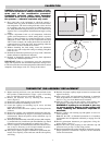
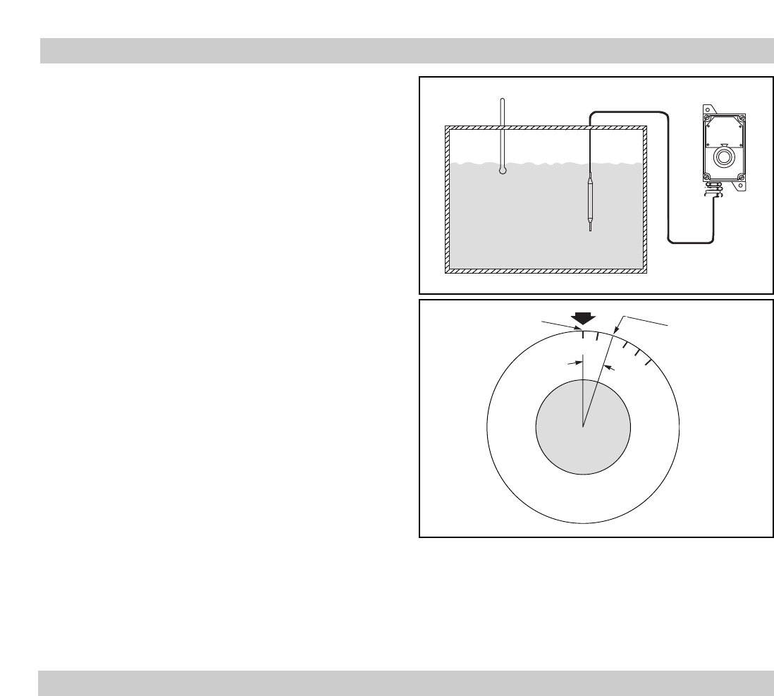
2. Compare adjustment knob cut off temperature indication
against actual temperature to which sensing bulb is exposed.
Figure 15 shows example of a control knob showing a control
indication of 250°F when true process temperature measured
230°F. In this example, the control knob must be rotated 20°
counterclockwise to bring the 230°F knob marking under the
index mark in order to recalibrate the control.
3. Without disturbing the shaft setting, loosen the thermostat
knob set-screw and re-align dial setting accordingly. Retighten
knob set-screw.
4. Recheck for thermostat operation as per steps 2 and 3 and make
further calibration adjustment if indicated.
5. Recheck of thermostat operation following final adjustment
completes the calibration procedure.
IMPORTANT: Under no circumstances must the temperature
range, and in particular, the maximum temperature setting of con-
trol be increased above maximum temperature indicated on control
nameplate. Such changes voids U.L. listing of the control.
1. Before removing enclosure cover, turn thermostat knob to the
OFF position (counterclockwise). Place a piece of masking
tape over the knob to keep it in the OFF position.
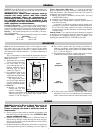
2. Remove the enclosure cover by removing four fastening
screws (Figure 5).
3. Remove the white shaft coupler for safe-keeping.
4. Remove the thermostat mounting screws (2).
5. Loosen the capillary-seal retaining cap set screws and then
remove the retaining cap.
Note: Do not remove the entire capillary seal fitting from the
enclosure.
6. Remove the capillary seals and thermostat from the enclosure.
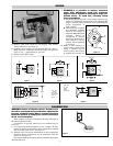
7. Remove the calibration cap (Figure 1) and insert pin from the
old thermostat. Rotate the position of the calibration cap, for
use in the next step.
8. With replacement thermostat in the OFF position (shaft complete-
ly counterclockwise), install insert pin and calibration cap. Install
calibration cap with same orientation as noted in step 7 above.
9. If excess capillary, on old thermostat, had been coiled in enclo-
sure, it may be necessary to coil an equal amount on replace-
ment thermostat per step 4D mounting instructions.
10. After proper capillary length is obtained on replacement ther-
mostat, insert capillary in the enclosure and thru the capillary
seal fitting.
11. Recheck for proper capillary length (external to enclosure) and
adjust if necessary.
12. Align spacer plate and replacement thermostat to mounting
holes in the bottom of enclosure using mounting screws (2 –
#10-32 x
3
/8 Lg.) to secure thermostat to enclosure.
13. Slide the capillary seals into the capillary fitting making sure
the capillary is positioned in the center groove of the seals.
WARNING: If capillary is not located in the cen-
ter groove properly, damage to the capillary will
result, rendering the thermostat inoperable or
unreliable.
14. Replace capillary seal retaining cap and tighten set screws to
lock in position.
Note: Per the NEC, all threaded connections in a hazardous
environment must be tightened sufficiently to engage five full
threads.
15. Rewire replacement thermostat per appropriate wiring dia-
grams (Figures 7 thru 11).
16. Replace the white nylon coupling on the calibration cap and
enclosure cover per step 7 of the wiring section.
17. Replacement thermostat control should be monitored to insure
proper operation. If calibration is required, see the calibration
section for instructions.
Thermometer
Load (Tank, vat, die or platen)
Indicated Temp.
True Temp
250
200
A
Figure 14
Figure 15
-4-