


1
2
3
4
1
2
3
4
Pilot
Light
Load
Line
Single Phase
Pilot Light
Load
Line
Single Phase
1
2
3
4
Pilot Light
Line
Load
Load
Two Circuit
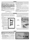
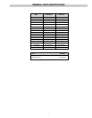
4. Remove white shaft coupler for safe-keeping while making
wiring connections (see Figure 6).
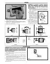
5. Connect wires according to wiring diagrams (Figures 7 thru 11).
Note: Electrical connections should be made with generous
loops of wire — approximately 6” per lead.
6. Replace white shaft coupler.
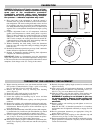
7. WARNING: It is possible to replace enclosure
cover with adjustment knob 180 rotational
degrees out of alignment resulting in large cali-
bration errors. To avoid this, carefully follow
these procedures.
A. Be sure that thermostat shaft is fully counter-clockwise (see
Figure 12). With thermostat knob held in the indicated OFF
position, carefully replace enclosure cover while feeling for
proper engagement of
shaft coupling.
B. With cover screws replaced
and moderately fastened,
check for full rotation of
dial knob. Note: Mild shaft
resistance should be
encountered. If satisfied,
that proper engagement of
shaft coupler is accom-
plished; finish tightening
cover screws.
8. Note: If load amperage or
voltage rating exceeds switch
rating, a contactor must be
used. Contactor and wiring to
be supplied by customer (see
-3-
WIRING
CALIBRATION
WARNING: Hazard of Electric Shock. Extreme care
should be exercised during calibration adjustments
because of shock hazard due to exposed electrical
terminals. Failure to comply can result in electrical
shock or electrocution.
These controls are factory calibrated to the range indicated on
the control adjustment knob.
If calibration is required, either one of two methods may be
followed.
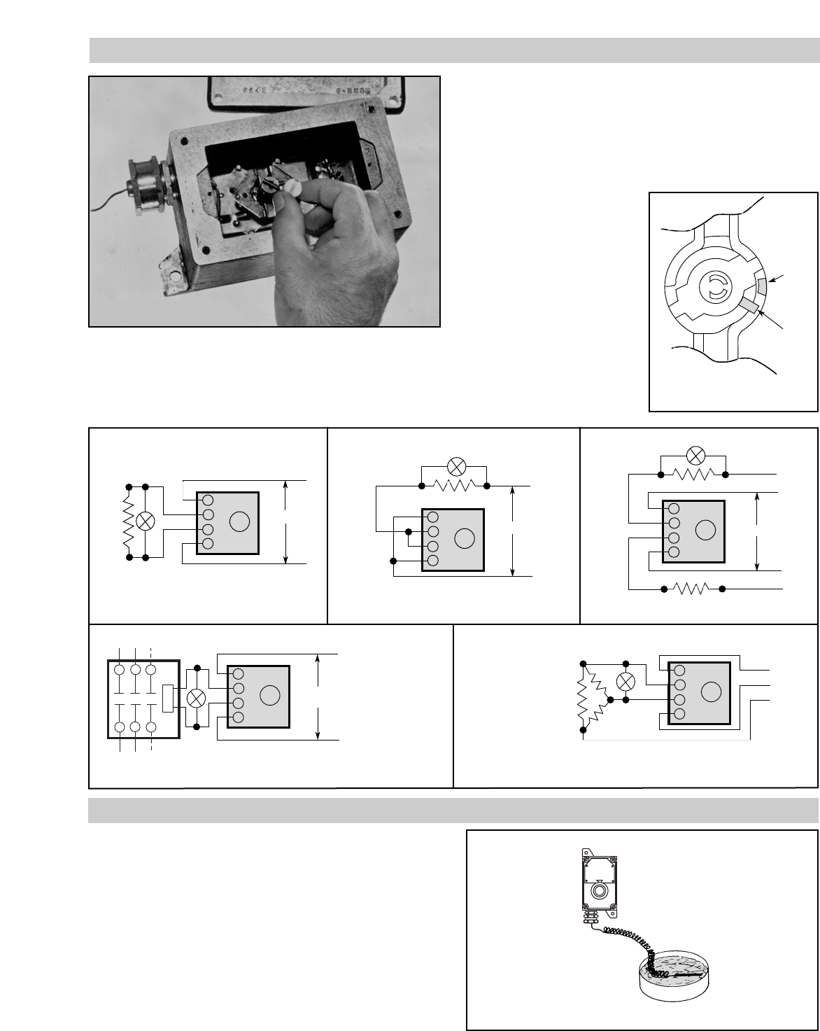
1. If accurate measurement standards are not available, the ther-
mostat can readily be adjusted to a known temperature standard
such as boiling water (212°). See Figure 13.
2. With the aid of an accurate thermometer or other temperature
measuring device, recalibration may be performed within the
process as in Figure 14.
For either method, the following general calibration procedures
should be followed.
Dial
Stop
Post
Stop
Tab
Figure 12
Figure 6
1
2
3
4
1
2
3
4
Pilot
Light
Line
Three Phase
when Load
Does Not
Exceed
Rating of
Thermostat
}
Three Phase
and Single
Phase when
Load Exceeds
Rating of
Thermostat
Control
Voltage
Line
Load
Pilot
Light
Contactor
Figure 13
Figure 7
Figure 8 Figure 9
Figure 10 Figure 11