


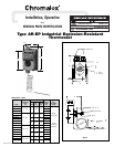

GENERAL
NOTICE: Type AR-EP controls are designed for temperature con-
trol service only. Because they do not fail safe, they should not be
used for temperature limiting duty.
WARNING: Users should install adequate back-up
controls and safety devices with their electric
heating equipment. Where the consequences of
failure may be severe, back-up controls are essen-
tial. Although the safety of the installation is the
responsibility of the user, Chromalox will be glad to
make equipment recommendations.
Principle of Operation — Control action of these thermostats is
provided through the principle of liquid volume change. With a
variation in temperature, the liquid in the sensing bulb expands or
contracts, causing a bellows to actuate the switching mechanism.
Housing — The control housing and cover assembly is of heavy-
duty cast aluminum.
Control Range — The following temperature ranges are available:
Fahrenheit
0° to 100° 200° to 550°
60° to 250° 300° to 700°
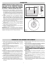
Process Temperature Differential — is variation in controlled
process temperature between maximum, when thermostat turns
OFF and minimum, when thermostat turns ON. This spread in
temperature may be minimized by —
1. Making sure control is mounted to vertical surface. (See Step
1, MOUNTING section.)
2. Avoiding excess heating capacity (oversized heaters).
3. Locating control sensing bulb in optimum position between
heat source and work.
In general, it is difficult to predict the actual operating dif-
ferential of a given process. Temperature differential may be as
low as 4°F for low range controls to as high as 17°F for high-
er range controls since the differential is a percentage function
of the dial range.
Packing Glands — If a sealed or leak-proof connection is required
at the point where the capillary enters the oven, tank, pipe or simi-
lar equipment, an appropriate packing gland is available as an
optional part. (Model CCF-25A, CCF-25D or CCF-25E)
WIRING
MOUNTING
WARNING: Hazard of Electric Shock. Disconnect all
power before wiring or servicing this control.
Failure to comply can result in electrical shock or
electrocution.
1. Electric wiring to heater must be installed in accordance with
National Electrical Codes and local codes. WARNING: Use
copper conductors only.
2. Entrance for wiring is provided by one
3
/4” NPT hole in the top
of the housing. Wiring to control housing must be in rigid con-
duit also in accordance with National Electrical Codes (NEC)
for hazardous locations.
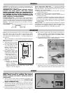
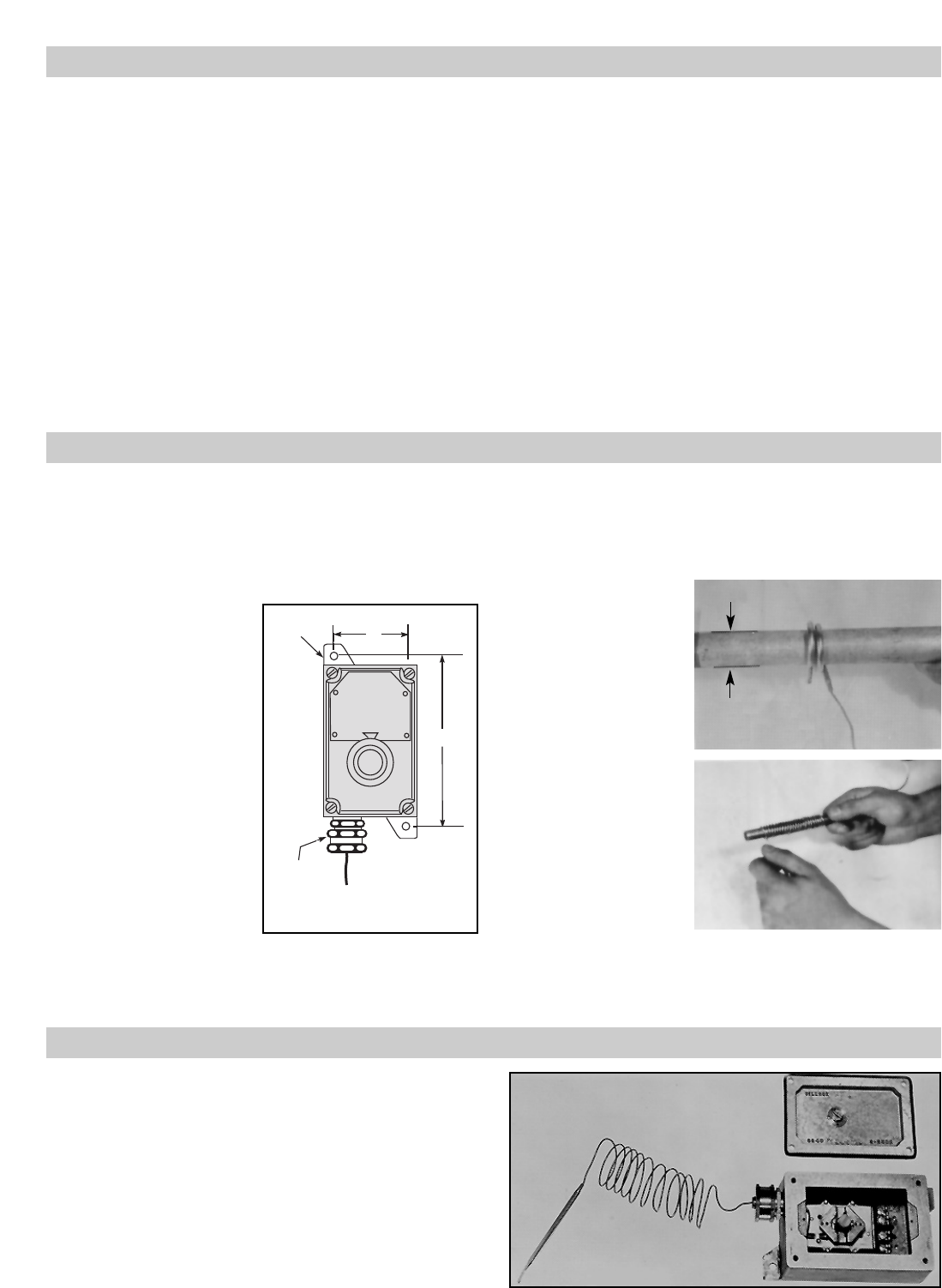
3. Set thermostat knob to OFF position and remove cover plate by
loosening and removing four (4) fastening screws (see Figure 5).
Note: Do not mount thermostat where it will be subject to vibra-
tion, shock, grease, dust, lint or corrosive vapors. Do not mount
adjacent to a large magnetic contactor, as vibration and shock will
cause thermostat to interact erratically — resulting in chattering of
the contactor.
The air temperature in and around the thermostat enclosure
should be kept as near to normal room temperature as possible...
never above 150°F.
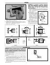
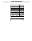
1. Thermostat must be mount-
ed in a vertical position only.
2. Use sheet metal or wood
screws through the two
5
/16”
diameter mounting holes in
mounting lugs to mount
control (see Figure 2).
3. For controlling platen or die
temperatures, insert entire
sensing bulb into drilled holes
selected for snug slip fit.
The longer, more sensi-
tive Style 9 bulbs should be
used for controlling air tem-
peratures or pipe line heating.
4. NOTICE:
A. Bending or deforming
sensing bulb will alter
control calibration —
requiring recalibration after installation. See CALIBRA-
TION section, page 3. If necessary, Style 9 bulbs can be
coiled to 1” I.D. (see Figure 3).
B. Do not kink capillary tube. The resulting constrictions in
fluid flow can destroy control function or broaden temper-
ature differential. Minimum capillary tube bending diame-
ter is
1
/2” I.D. (see Figure 4).
C. Any deformations of bulb or capillary that result in leakage
of fluid from control renders control inoperative.
D. Avoid passing control capillary tube through zones whose
temperature is in excess of controlled process temperature.
Erratic control or destruction of control function may result.
Mounting
Lugs
Capillary
Seal
Fitting
3"
7 / "
3
8
Figure 2
Figure 3
(Sensing Bulb)
Figure 4
(Capillary Tube)
Figure 5
Do Not
Bend or Kink
Crimped End
1
/2”
Rod
1”
-2-