


7
1. Do not operate heater at voltages in excess of that stamped on the
heater since excess voltage will shorten heater life.
2. Always maintain a minimum of 6 to 8” of liquid above the heated
portion of the element to prevent exposure of the effective heated
length. If the heater is not properly submerged, it will overheat and
shorten heater life. DO NOT OPERATE HEATER IF DRY.
3. Keep heating elements above sediment deposits.
4. Low Megohm Condition — The refractory material used in elec-
tric heaters may absorb moisture during transit, storage or when
subject to humid environments that will reduce the cold insulation
resistance (low megohm). Low megohm may result in a high leak-
age current to ground and nuisance trips of ground fault protection
equipment. Normally, the megohm value increases after heat-up.
Typical insulation valves are 5 megohm or greater on complete
assemblies or 20 megohm on individual unsealed elements. It is
recommended that heaters with 1 megohm or less be dried out
before applying full power. If dried properly, low megohm will not
effect heater life or efficiency.
To correct a low megohm condition, remove terminal enclosure
cover, gaskets, and terminal hardware. Bake heaters in an oven at
300 to 500˚F for several hours or preferably overnight.
An alternate procedure is to cycle the heater in 10 to 15 minute
periods at low voltage until megohm values are normal. Sheath
temperatures should not exceed 350˚F.
NOTE: Low megohm on heating elements with epoxy or hermetic
seals cannot be serviced in the field. Typical resistance val-
ues when sealed are 200 megohm or greater. Contact Chro-
malox service center at number listed.
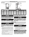
OPERATION
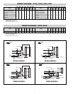
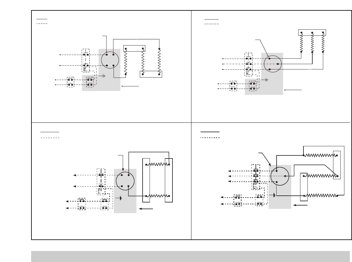
Term. Block
Contactor
L1
L2
Thermostat
Junction Box
120V
or
240V
Low
Liquid
Control
Factory
Field
Term. Block
Contactor
L1
L2
Thermostat
Junction Box
120V
or
240V
Low
Liquid
Control
Factory
Field
L3
WIRING DIAGRAM 7
WIRING DIAGRAM 8
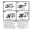
Factory
Field
120V
or
240V
Contactor
Thermostat
Low
Liquid
Control
L1
L2
Term. Block
Junction Box
L3
120V
or
240V
Contactor
Thermostat
Low
Liquid
Control
L1
L2
Term. Block
Junction Box
Factory
Field
WIRING DIAGRAM 6
WIRING DIAGRAM 5