


ELECTRIC SHOCK HAZARD. Any installation involv-
ing electric heaters must be performed by a quali-
fied person and must be effectively grounded in
accordance with the National Electrical Code to
eliminate shock hazard.
1. Electric wiring to heater must be installed in accordance with the
National Electrical Code and with local codes by a qualified per-
son. CAUTION: Use copper conductors only.
2. When element wattages are not equal, heaters must not be con-
nected in series.
3. Electrical wiring to heater should be contained in rigid conduit or
in sealed flexible conduit to keep corrosive vapors and liquids out
of the terminal enclosure. If high humidity is encountered, the con-
duit should slope away from the heater.
4. If flexible cord is employed, a watertight connector should be used
for entry of the cord into the terminal enclosure. Outdoor applica-
tions require liquid-tight conduit and connectors.
5. Bring the power line wires through the opening in the terminal
enclosure.
6. Heaters are prewired and tagged for easy installation of electrical
wiring to the heater. Tagging of the individual circuits of
Chromalox Industrial Over-The-Side Immersion heaters is shown
in the following tabulations. Refers to Type TLC, TLO, TLS, TLI,
KTLC, KTLO, KTLS, KTLI, KBLC, KBLS, BLCK, and BLCS
Series heaters.
7. Make sure heater, is grounded by attaching ground conductor,
traceable back to service entrance, to the ground terminal located
inside the terminal enclosure. If heater is used in an electroplating
tank, the heater should be grounded externally to the tank wall to
minimize stray plating currents in heater sheath that may cause
sheath corrosion.
8. Check for loose terminal connections and tighten if necessary.
Made to order items are prewired and tagged at the factory. Wiring
of made to order items may differ from those shown in the tabu-
lations. Carefully check voltage and phase on the heater name-
plate and select either the appropriate wiring shown above or
check for the appropriate wiring diagram in the heater termi-
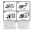
nal enclosure. For reference purposes, some typical wiring dia-
grams are shown in the following figures.
5
WIRING
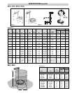
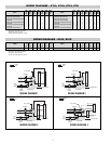
WIRING DIAGRAMS – TLC, TLO, TLS, TLI
120V 120V 240V 240V 480V 480V 480V 120V 120V 240V 240V 480V 480V 480V
Model 1ø 3øΔz 1ø 3øΔz 1ø 3øΔz 3øY Model 1ø 3øΔz 1ø 3øΔz 1ø 3øΔz 3øY
Fig. Fig. Fig. Fig. Fig. Fig. Fig. Fig. Fig. Fig. Fig. Fig. Fig. Fig.
TLC, TLI and TLS 210 — — 1 — 1 — — TLO 310 — — 3 4 3 4 —
TLC, TLI and TLS 212 — — 1 — 1 — — TLC, TLI and TLS 312 — — 3 4 3 4 —
TLC, TLI, TLO and TLS 220 1 — 1 — 2 — — TLC, TLI and TLS 315 — — 3 4 3 4 —
TLO 230 1 — 1 — 1 — — TLC, TLI and TLS 318 — 3 4 3 4 —
TLC, TLI, TLO and TLS 240 1 — 1 — 1 — — TLC, TLI, TLO and TLS 330 3 4 3 4 5 4 6
TLO 250 1 — 1 — 1 — — TLO 345 3 4 3 4 3 4 —
TLC, TLI, TLO and TLS 260 1 — 1 — 1 — — TLC, TLI, TLO and TLS 360 3 4 3 4 3 4 —
TLO 270 — — 1 — 1 — — TLO 375 3 4 3 4 3 4 —
TLC, TLI and TLS 280 — — 1 — 1 — — TLC, TLI, TLO and TLS 390 3 4 3 4 3 4 —
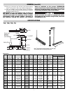
Note: Use wire size and type specified by NEC.
480V heaters require 600V wire per NEC.
480V heaters require a contactor.
Contactor and wiring supplied by customer.
INSTALLATION (cont’d.)
9. To prevent moisture accumulation in cryogenic applications or
when heater is exposed to freezing temperatures:
A. Slope conduit away from enclosure (drip loop).
B. Seal all conduit openings to moisture/explosion resistant ter-
minal enclosure.
C. Insulate terminal enclosure.
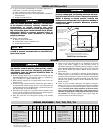
FIRE OR SHOCK HAZARD. Moisture accumulation
in the element refractory material, element over-
temperature, or sheath corrosion can cause
ground fault to the element sheath, generating arc-
ing and molten metal. Install Ground Fault Circuit-
Interrupter (GFCI) to prevent personal injury or
Equipment Ground Fault Protection to prevent
property damage.
10. Heaters with floor flange:
A. Remove electrical enclosure.
B. Mount heater to tank or manhole cover.
C. Install electrical enclosure.
Fittings into electrical enclosure must be properly
sealed to prevent contamination of electrical con-
tacts from vapors.
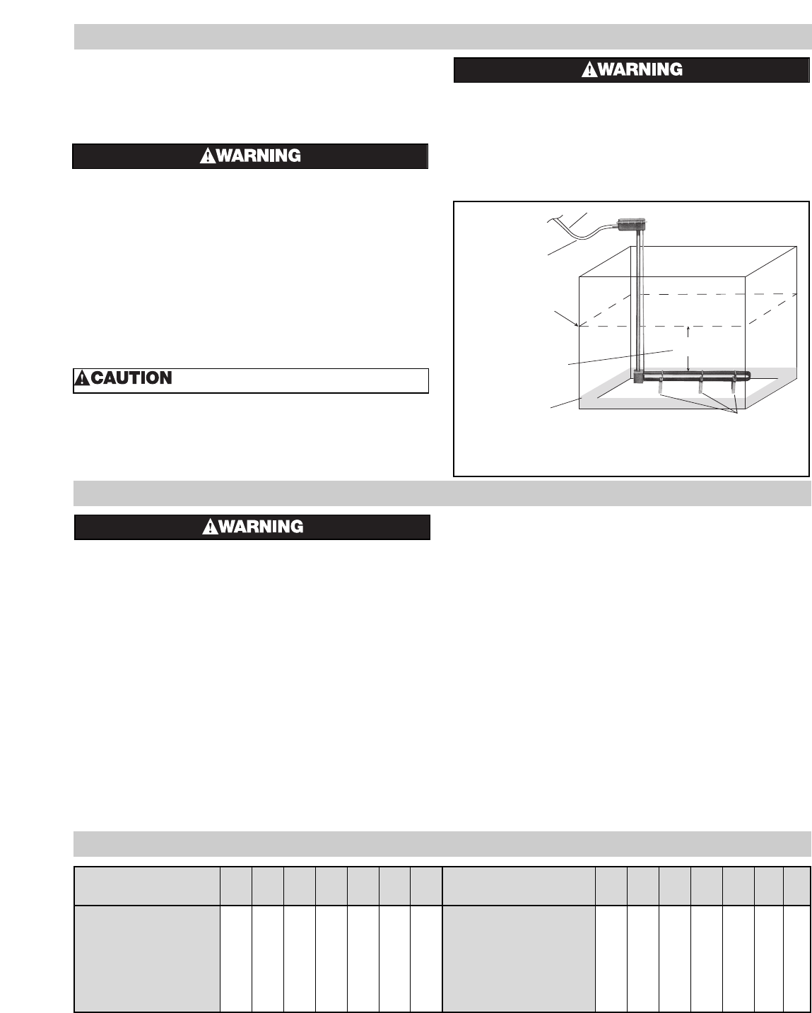
FIRE OR EXPLOSION HAZARD. If the heater is not
properly submerged, the heating elements will over-
heat and could result in a fire or damaged equipment.
NOTE: If heating in closed vessels, controls and
backup controls must be used to prevent buildup of
temperature and/or pressure. Maximum pressure
rating is 50 PSI.
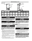
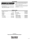
Drip Loop recommended to
minimize passage of moisture
along wiring into terminal
wiring connections.
Expected Low Liquid Level
Always maintain a minimum of
6 to 8" of liquid above the heated
portion of the element to prevent
exposure of the effective
heated length.
Expected maximum
sediment level
Sludge Legs
NOTE: Locate the heater as low as possible for maximum
heated liquid storage capacity. Heat does not move downward.
6 to 8"
Minimum
Suitable Wiring
FIGURE 3 Open Tank Illustration
!