


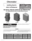

6
MAINTENANCE
The Chromalox STAR-TG tip over cutout with ground fault
sensor provides a reliable and cost effective method for sensing
ground faults and to shut off the heater in case of tip-over. The pur-
pose of the ground fault control is to monitor for ground faults,
sense potential heater failure symptoms and to protect equipment.
The current-carrying wires are routed through the current
transformer on the control. When ground current reaches the level
set by the trip point adjustment, (.03 amps), the relay trips, illumi-
nates the tripped LED and provides an output signal which de-
energizes the magnetic contactor.
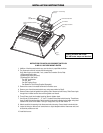
ELECTRIC SHOCK HAZARD. Disconnect all power
to heater before installing or servicing kit(s).
Failure to do so could result in personal injury or
property damage. Kit(s) must be installed by a
qualified person in accordance with the National
Electrical Code, NFPA 70.
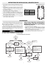
If heating element(s) fail to operate:
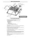
1. Open door of enclosure. DANGER: Hazard of Electric
Shock.
2. If "Tripped" indicator is not on, check for blown fuses or failed
electrical components in the heater’s electrical system includ-
ing the tip over trip mechanism.then this indicates one or more
heating elements are about to fail.
3. Check pendulums on the tip over switch mechanisms to be sure
they are not blocked.
4. If the "Tripped" indicator is on, then this indicates one or more
heating elements are about to fail. Disconnect power and fol-
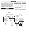
low the GF Troubleshooting Diagram below.
Tripped Indicator
Light is On
Is this the
initial
installation?
Is this the first
time heater is
used for the
season?
Is the set point of
the GF sensor set
at a value less than
.03 amps?
Did the problem
occur after
working properly
during part of this
heating season?
This condition indicates
at least one element is
about to fail.
Call Chromalox
Service Dept.
1 800-368-2493
Close cover.
Does the
heater
operate?
Does the heater
operate?
1. Replace all elements.
2. Flip toggle switch back
and forth, one time to
reset GF sensor.
Do you want to
reduce future
down time and
maintenance
costs?
1. Turn set point dial
clockwise to .03 amps.
2. Flip toggle switch mounted ontop
of enclosure back and forth one
time, (this resets the GF sensor).
Unbuss wiring, check insulation resistance
on each element.
1. Each element to have at least 10 Meg
terminal to sheath.
2. If element does not have at least 10 Meg.
dry out element by applying half of the
rated voltage for one hour.
3. Rebuss elements, re-energize heater, flip
toggle switch back and forth, one time
to reset GF sensor.
Does the heater
operate?
Call Chromalox
Service Dept.
1 800-368-2493
Does the
heater
operate?
Close all covers.
Unbuss wiring, check insulation resistance
on each element.
1. Each element to have at least 10 Meg
terminal to sheath.
2. If element does not have at least 10 Meg.
dry out element by applying half of the
rated voltage for one hour.
3. Rebuss elements, re-energize heater, flip
toggle switch back and forth, one time
to reset GF sensor.
START
Yes
No
Yes
Yes
Yes
Yes
Yes
Yes
Yes
Yes
No
No
No
No
No
No
No
Close all covers.
Close all covers.
TG TROUBLESHOOTING DIAGRAM