


4
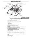
INSTRUCTIONS FOR INSTALLING WALL MOUNTED STAR-GF
1. Check voltage on heater nameplate and STAR-GF to make cer-
tain voltages are the same. If voltages do not match, consult
factory.
2. The STAR-GF will provide ground fault protection for STAR
Radiant heaters. The number of heaters serviced by one (1)
STAR-GF is dependent on the number and length of the heat-
ing elements. See Table 2.
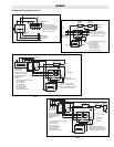
3. See Instruction Sheet PG434 (provided with heater) for
IMPORTANT INSTRUCTIONS and WIRING.
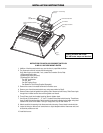
4. Using the STAR-GF as a template mark mounting holes on
wall. Use an anchoring method adequate to support the weight.
5. Wire between STAR-GF and heater, wire to terminal block.
Service entrance wiring to be made to contactor connectors.
For wire gage see Table 1 of PG434.
6. The ground fault sensor has been factory set at .03 Amps, DO
NOT CHANGE THE SETTING.
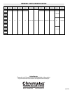
Table 2
Heater Model Max. No. of Heaters
STAR-02A 6
STAR-05A 3
STAR-06A 2
STAR-14A 1
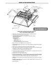
STAR-GF Mounting Dimensions
8-1/2"
6"
10-3/4"
10"
6"
3/4
3/4
5/16 Dia.
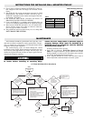
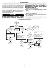
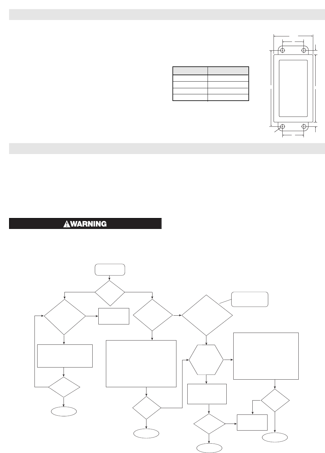
Tripped Indicator
Light is On
Is this the
initial
installation?
Is this the first
time heater is
used for the
season?
Is the set point of
the GF sensor set
at a value less than
.03 amps?
Did the problem
occur after
working properly
during part of this
heating season?
This condition indicates
at least one element is
about to fail.
Call Chromalox
Service Dept.
1 800-368-2493
Close cover.
Does the
heater
operate?
Does the heater
operate?
1. Replace all elements.
2. Flip toggle switch back
and forth, one time to
reset GF sensor.
Do you want to
reduce future
down time and
maintenance
costs?
1. Turn set point dial
clockwise to .03 amps.
2. Flip toggle switch mounted ontop
of enclosure back and forth one
time, (this resets the GF sensor).
Unbuss wiring, check insulation resistance
on each element.
1. Each element to have at least 10 Meg
terminal to sheath.
2. If element does not have at least 10 Meg.
dry out element by applying half of the
rated voltage for one hour.
3. Rebuss elements, re-energize heater, flip
toggle switch back and forth, one time
to reset GF sensor.
Does the heater
operate?
Call Chromalox
Service Dept.
1 800-368-2493
Does the
heater
operate?
Close cover.
Close cover.
Close cover.
Unbuss wiring, check insulation resistance
on each element.
1. Each element to have at least 10 Meg
terminal to sheath.
2. If element does not have at least 10 Meg.
dry out element by applying half of the
rated voltage for one hour.
3. Rebuss elements, re-energize heater, flip
toggle switch back and forth, one time
to reset GF sensor.
START
Yes
No
Yes
Yes
Yes
Yes
Yes
Yes
Yes
Yes
No
No
No
No
No
No
No
The Chromalox STAR-GF ground fault sensor provides a reli-
able and cost effective method for sensing ground faults. The pur-
pose is to monitor for ground faults, sense potential heater failure
symptoms and to protect equipment.
The current-carrying wires are routed through the current
transformer on the control. When ground current reaches the level
set by the trip point adjustment, (.03 Amps), the relay trips, illu-
minates the tripped LED and provides an output signal which de-
energizes the magnetic contactor.
ELECTRIC SHOCK HAZARD. Disconnect all power
to heater before installing or servicing kit(s).
Failure to do so could result in personal injury or
property damage. Kit(s) must be installed by a
qualified person in accordance with the National
Electrical Code, NFPA 70.
If heating element(s) fail to operate:
1. Open door of enclosure. DANGER: Hazard of Electric
Shock. If "Tripped" indicator is on, this indicates one or more
heating elements are about to fail. Disconnect power and fol-
low the GF Troubleshooting Diagram below.
2. If the "Tripped" indicator is not on, check for blown fuses or
failed components within the heater's electrical system.
MAINTENANCE
GF TROUBLESHOOTING DIAGRAM