


2
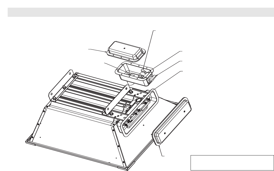
Cover
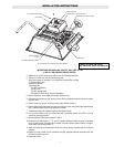
(Step 4)
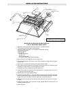
3 Pole Terminal Block w/Ground
(Step 8)
Opening for 1" Conduit Fitting
(Step 8)
3 Pole Disconnect Switch
On-Off Handle
Chase Nipple and Gasket
(Step 5)
Cover
(Step 3)
INSTALLATION INSTRUCTIONS
INSTRUCTIONS FOR INSTALLING DISCONNECT SWITCH ON
6 AND 13.5 KW FIXED RADIANT HEATERS
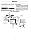
1. Addition of the disconnect switch assy must be done by a qualified electrician.
2. The disconnect switch kit includes the following parts.
Verify that all parts are included, if not, contact the Chromalox Service Dept.
(1)Disconnect Switch Assy
(2)Mounting Bracket (Not Used)
(3)Hardware Kit: (Not Used)
Two 3/8” Lockwashers
Two 3/8” Nuts
One Self Tapping Screw
One Gasket for Cord Fitting (Supplied Separately)
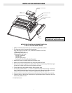
3. Remove the screws in the heater terminal box. Remove cover.
4. Remove cover from disconnect switch assy using same method as Step3.
5. Remove Chase nipple and gasket from opening end of disconnect switch assy. Slide Chase nipple
through hole in heater terminal box and then gasket over threads.
6. Thread Chase nipple into threaded coupling. Wrench tighten nipple.
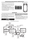
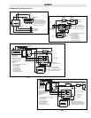
7. Uncoil three (3) leads marked “1”, “2”, and “3” located in disconnect switch housing. Thread these
three (3) leads through the nipple. Attach leads to the terminals indicated on the heater wiring label
located on the cover of the heater. If using for single phase, cap off lead marked “3”.
8. Attach conduit to the opening in the disconnect switch housing. Connect leads to terminal block.
9. Inspect all wiring to make sure all connections are tight, adequate electrical clearances exist, and
all electrical practices are met.
10.Install both covers.
Drawing shows 6 kW heater.
13.5 kW heater steps are identical.