


2150 N. RULON WHITE BLVD., OGDEN, UT 84404
Phone: 1-800-368-2493 www.chromalox.com
Table 3: Service Supply Wiring Sizes
Recommended Minimum supply wire sizes are listed in the table
below:
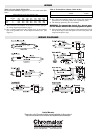
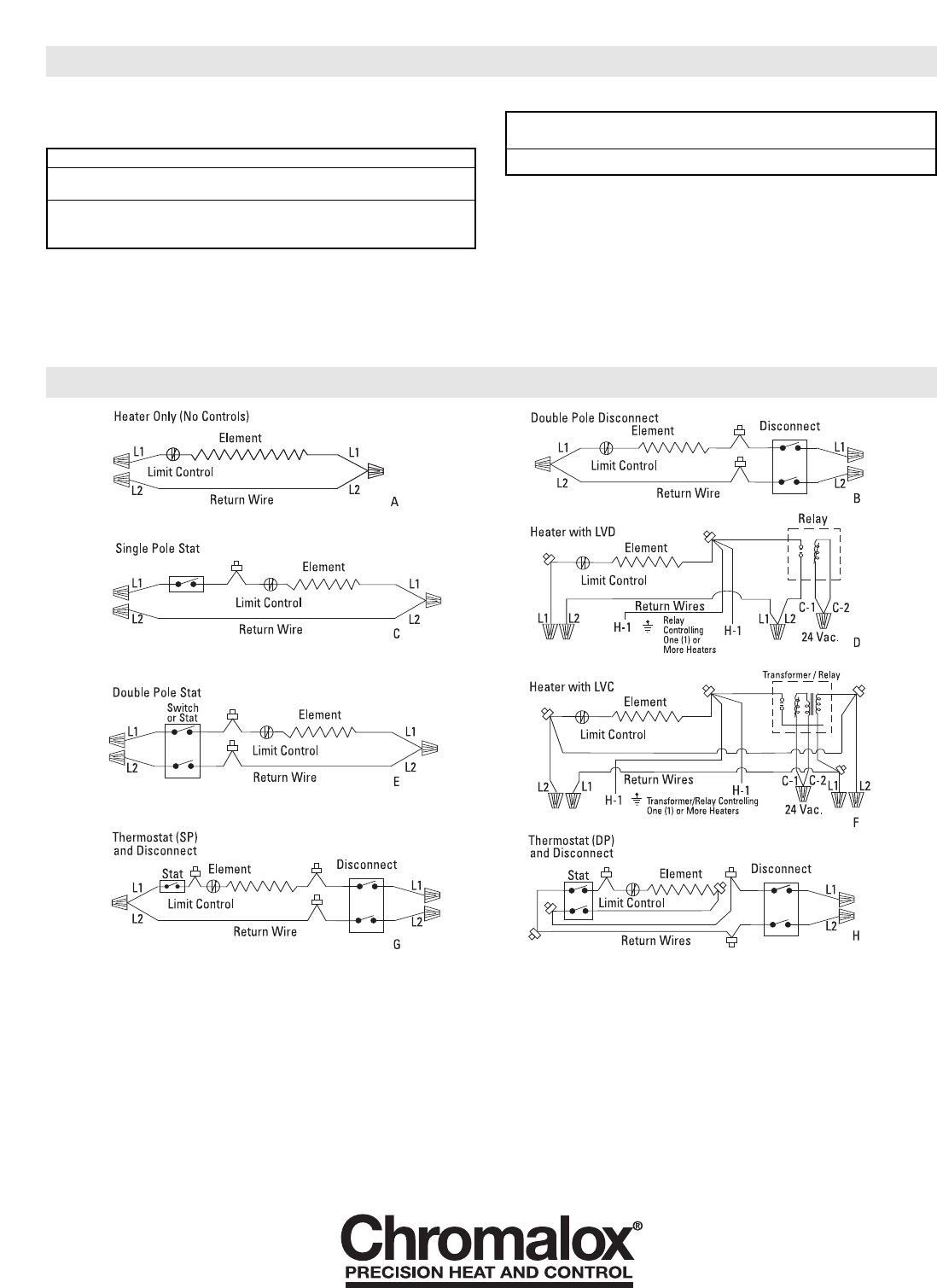
1. Wire all heaters and controls in accordance with the appropri-
ate wiring diagram provided on page 4.
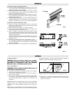
2. Run a ground jumper from the ground screw in one terminal
box to the ground screw in the adjacent terminal box. (See
Figure 4.)
Table 4: Terminal Box Volumes (Cubic Inches)
3. Do a final and complete check of all wiring, then replace the
terminal box covers being careful not to pinch any wires.
4. The front/top panel may now be installed.
WARNING: To prevent the risk of fire, do not oper-
ate the heater without the front/top panels in place.
5. Place the front panel over the flange of the bottom panel. Hook
the top back edge of the front panel over the back panel, and
snap onto the plastic clips.
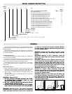
Maximum Watts Per Circuit Using 75 Degree C. Wire
Rough In
Wire Size 120V 208V 240V 277V 347V 480V 600V
14 1440 2496 2880 3324 4164 5760 7200
Copper 12 1920 3328 3840 4432 5552 7680 9600
Wire 10 2880 4992 5760 6648 8328 11520 14400
Heater Style Left Hand Box Right Hand Box
4” Wide 5” Wide
CAF-6, CCAS-8 33.25 41.50
WIRING
WIRING DIAGRAMS
Limited Warranty:
Please refer to the Chromalox limited warranty applicable to this product at
http://www.chromalox.com/customer-service/policies/termsofsale.aspx.