


Draft Barrier Heater Installation (Wall)
1. Once the correct mounting height is established, scribe or snap
a level line on the wall to maintain each heater back plate in
horizontal alignment, when mounting.
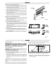
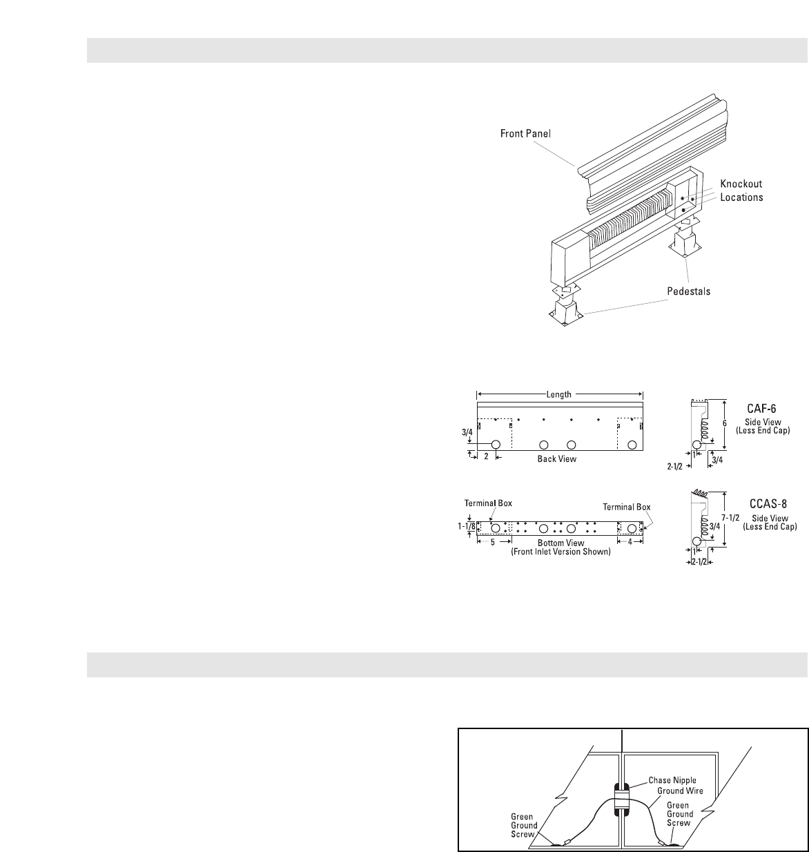
2. Remove heater front cover by lifting top rear edge to unsnap
cover from back plate (store cover in safe location to avoid
damage to the finish). (See Figure 2).
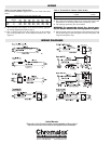
3. Remove all appropriate knockouts from terminal boxes, partic-
ularly terminal box end knockouts when installing continuous
run heating. (See Figure 3).
4. Mount the back panel to the wall using suitable fasteners (not
supplied). Should the wall surface be uneven, secure the heater
backplate to the high spots only to avoid a distorted appearance.
Draft Barrier Heater Installation (Floor)
1. Unpack the heater and pedestal(s) from the carton (The
pedestals are packed at the end of carton) and lift the front/top
panels up and off the heater.
2. Disassemble the pedestal base from the pedestal pad.
3. Remove the desired terminal box cover(s) and supply wire
entry knockouts from the terminal boxes.
4. Secure a pedestal to each end of the heater bottom with #8
screws provided aligning the back and front edges of the pad
with the heater. This will align the supply entry knockout with
opening in pedestal pad.
TIP:
Units longer than 4 feet will be provided with 3 or more
pedestals. The extra pedestals should be used to support the
middle of heaters.
5. Place heater on the pedestal base(s) and tighten all screws.
TIP:
The height of the heater can be adjusted on the pedestal to
aid in leveling the heater by loosening the securing bolt at the
side of the pedestals.
6. Remove the terminal box cover and proceed to wiring instructions.
GENERAL
WIRING
Ground Continuity —
WARNING: Hazard of Electric Shock. Any installa-
tion involving electric heaters must be effectively
grounded in accordance with the National
Electrical Code to eliminate shock hazard.
Prior To Installation —
WARNING: Hazard of Electric Shock. Disconnect all
power before installing heater.
1. All branch circuit and service supply wiring must be complet-
ed to the heater terminal box location.
2. Check heater nameplate ratings to be sure heater voltage is
same as service supply.
3. Service supply entry is usually made to one heater terminal box
(see Figure 3) with through wiring (Factory Installed) being
used for interconnection of all heaters in a continuous run
installation.
Note: When heaters are mounted end to end, remove the finishing
end plate, install a chase nipple and locknut in the terminal box
end knockout to ensure grounding continuity and to protect the
wiring.
Where heaters are spaced apart, remove the finishing end plate,
and use rigid conduit (Provided by customer) for through wiring
and ground continuity. Do not exceed the allowable number of
conductors allowed by the National electrical code.
Note: See Table 3 for recommended service supply wire sizes.
4. Knockouts are provided at the back, bottom and ends of all
heater backs (see Figure 3). Terminal boxes are located at both
ends of every heater.
Figure 3
Figure 2
Figure 4