


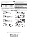
MODEL NUMBER DESCRIPTION
This document explains the correct procedure for the installa-
tion and safe operation of all models of Draft Barrier and Pedestal
Mounted Heaters.
Draft Barrier Heating Systems are designed to be installed in
accordance with the National Electrical Code and with local codes
by a qualified person.
General Information —
Draft Barriers and Pedestal Mounted Heaters are intended for
wall, sill or floor mounting.
The heaters are designed so that they may be used as an indi-
vidual cabinet convector, in a wall-to-wall configuration or as an
end-to-end continuous perimeter room heating system.
Draft Barrier heating systems are supported by a wide selec-
tion of controls and accessories designed to solve any heating
requirement.
Before You Unpack —
1. Make certain that the number of cartons received agrees with
the Bill of Lading, Packing List and original order. Also check
that the correct style (Model) and color have been shipped.
2. Every heater is carefully inspected and shipped with a clear
Bill of Lading.
Obvious external and/or concealed damage must be reported to
the carrier for remedy.
WARNING: Hazard of Fire
1. DO NOT INSTALL HEATERS AGAINST ANY HIGH-
LY COMBUSTIBLE SURFACES SUCH AS LOW
DENSITY CELLULOSE FIBRE.
2. DO NOT LOCATE HEATER BELOW ELECTRICAL
CONVENIENCE RECEPTACLES.
3. DO NOT STORE OR USE GASOLINE OR FLAMMA-
BLE LIQUIDS IN THE VICINITY OF THE HEATERS.
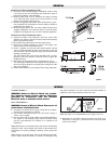
WARNING: Hazard of Fire. The normal operating
temperatures of cabinet convectors are relatively
high and proper operation requires free circulation
of room air through the heating element. Bottom
air inlet heaters must be mounted with minimum of
2” from finished floor.
WARNING: Hazard of Fire. Keep electrical cords,
drapes, rugs and other furnishings away from the
heater.
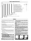
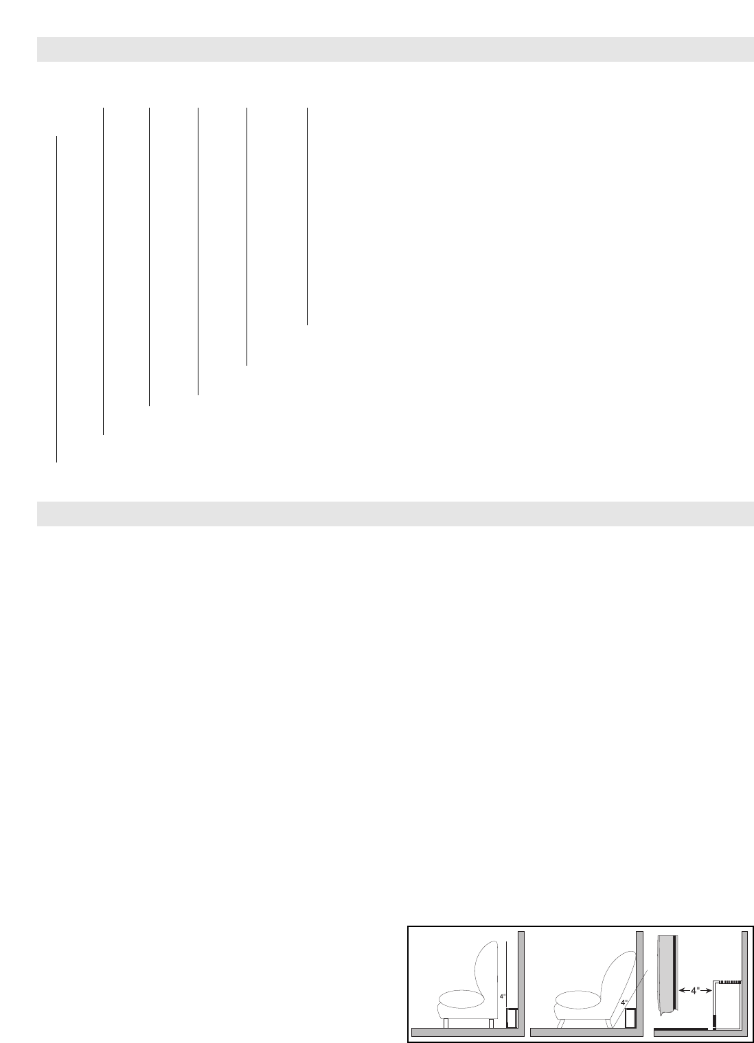
WARNING: Hazard of Fire. Furniture must be
placed no closer than four inches from the heater
(see Figure 1)
WARNING: Hazard of Fire. Drapes must clear the
top of heater by at least twelve inches; or, if floor
length drapes are used, they must clear the fin-
ished floor by three inches and the minimum clear-
ance from the back fold to the front cover should
be at least four inches (see Figure 1)
WARNING: Hazard of Fire. When the floor is to be
finished in carpet, allow clearance under the
heaters and corners for carpet installation. Bottom
air inlet heaters are to be mounted a minimum of
2” from the finished floor.
WARNING: Hazard of Fire. Rugs may be placed up
to a heater provided that they are not of a thick-
ness that would block the air-intake. Bottom air
inlet heaters are to be mounted a minimum of 2”
from the finished floor.
Figure 1: Furniture & Drapes
GENERAL
CAF-6 B 2 05 11 01 A1
or Refer to
CCAS-8 Code Control Options (Factory Installed) Wiring Diagram
00 = No Optional Control A
A1 = Built-in SP tamperproof thermostat 120 - 277V C
A2 = Built-in DP tamperproof thermostat 120 - 277V E
F1 = Built-in SP adjustable thermostat 120 - 277V C
F2 = Built-in DP adjustable thermostat 120 - 277V E
A4 = Built-in 24V low voltage relay 120 - 277V D
A5 = Built-in 24V low voltage relay and transformer 120 - 277V F
A8 = Built-in disconnect switch, rated 277V@20A B
B1 = Built-in SP tamperproof thermostat and disconnect G
B2 = Built-in DP tamperproof thermostat and disconnect H
F3 = Built-in SP adjustable thermostat and disconnect G
F4 = Built-in DP adjustable thermostat and disconnect H
D1 = Built-in low voltage relay and disconnect
D2 = Built-in low voltage transformer and disconnect
Painted Anodized
68 = Almond 07 = Bronze
02 = White 10 = Clear
Code Voltage/Phase
11 = 120/1 21 = 208/1 31 = 240/1 41 = 277/1
Code Wattage (See Table)
Code Length
2 = 2 ft. 3 = 3 ft. 4 = 4 ft. 5 = 5 ft. 6 = 6 ft. 7 = 7 ft. 8 = 8 ft. 9 = 9 ft. 10 = 10 ft.
Code Inlet Location
F = Front B = Bottom
Type
TABLE 2