


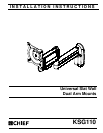


KSG110 Installation Instructions
6
CAUTION: IMPROPER INSTALLATION CAN LEAD TO
DISPLAY FALLING CAUSING SERIOUS PERSONAL
INJURY OR DAMAGE TO EQUIPMENT! Inadequate thread
engagement in display may cause display to fall! Back out
screws ONLY as necessary to allow installation of Centris
bracket!
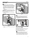
1. Ensure Centris cup is able to swivel and tilt easily, yet still
be tight enough to hold display in desired position. Adjust
as required before proceeding. See "ADJUSTMENT" for
detail.
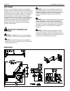
2. Using Phillips screwdriver, carefully install two screws (G1)
into the upper mounting holes on the display. Thread
screws completely into display, then back out 3 complete
turns.
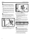
3. Align two screws (G1) (installed on the back of the display
in the previous step) with the two top teardrop mounting
holes on the Centris cup.
CAUTION: IMPROPER INSTALLATION CAN LEAD TO
DISPLAY FALLING CAUSING SERIOUS PERSONAL
INJURY OR DAMAGE TO EQUIPMENT! Smaller area of
teardrop mounting holes must be facing downward for proper
installation. Reposition Centris cup if required.
Figure 4
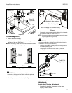
4. Using Phillips screwdriver, install two screws (G1) through
the lower mounting holes in Centris cup into the display.
5. Tighten all screws (G1). Do not overtighten!
Figure 5
6. Proceed to "CABLE MANAGEMENT."
Swing Arm Recessed Display Installation
1. Ensure Centris bracket is able to swivel and tilt easily, yet
still be tight enough to hold display in desired position.
Adjust as required before proceeding. See
"ADJUSTMENT" for detail.
2. Carefully place display face down on a clean and dry
surface.
3. Determine depth of recessed mounting holes relative to
back surface of display.
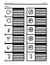
4. Select proper length spacer and screw from table below:
IMPORTANT ! : All spacers used should be the same length.
If the recess depths result in multiple spacer lengths, then
select the longer spacer.
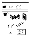
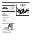
5. Place the four (G4 or G5) spacers over each mounting hole
on the back of display. (See Figure 6)
6. Orient mount so that mounting holes in the Centris cup are
aligned with the holes in the spacers (G4 or G5); rotate the
Centris cup as required (See Figure 6).
CAUTION: IMPROPER INSTALLATION CAN LEAD TO
DISPLAY FALLING CAUSING SERIOUS PERSONAL
INJURY OR DAMAGE TO EQUIPMENT! Using screws of
improper size may damage your display! Proper screws will
easily and completely thread into display mounting holes.
7. Using Phillips screwdriver, install four screws (G2 or G3)
through the mounting holes in Centris cup, through the
spacers (G4 or G5), into display (See Figure 6).
8. Tighten all four screws. Do not overtighten!
9. Return to mount installation section to continue.
G1 x 2
Centris Cup
3
2
IF recess DEPTH is: THEN use spacer: AND screw:
3/8" or less G4 (3/8" long) G2 (G4 x 20mm)
More than 3/8" up to
and including 3/4"
G5 (3/4" long) G3 (G4 x 30mm)
G1 x 2
Centris Cup
4