


CM2 Installation Instructions
12
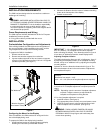
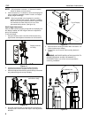
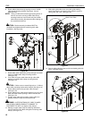
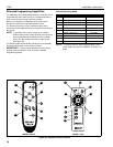
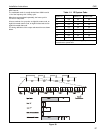
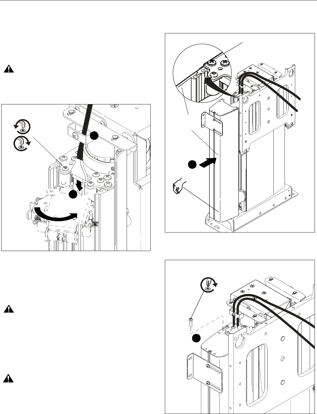
6. Route cable(s) down through opening at rear of middle
cable clamp mounting bracket. (See figure 19) and
(See figure 20)
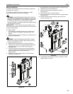
NOTE: If plug on cable will not fit through opening loosen or
remove one screw securing middle cable clamp
mounting bracket to mount frame and pivot middle
cable clamp mounting bracket to the side until plug can
be routed behind bracket.
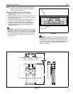
CAUTION: Bracket mounting hardware MUST be
reinstalled and tightened before continuing with cable
installation. (See figure 20)
Figure 20
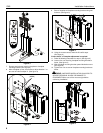
7. Route cable under cable pulley and up through front cable
clamp on middle cable clamp mounting bracket.
(See figure 19)
8. Loop cable and route cable down through side cable
clamp(s) on middle cable clamp mounting bracket.
(See figure 19)
CAUTION: Cables must not extend higher than 1" (25mm)
above cable mounting bracket when looped! (See figure 19)
9. Route cable(s) down through lower cable clamp(s).
(See figure 19)
10. Route cable through cable access opening in top of mount
base and cable access opening in side of mount base.
(See figure 19)
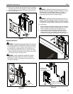
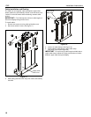
11. Tighten upper cable clamp making certain cables are
properly seated in clamp and are not pinched.
WARNING: OVERTIGHTENING OF CABLE CLAMPS
CAN CRUSH CABLES LEADING TO DAMAGE TO
EQUIPMENT! DO NOT over tighten cable clamps.
12. Starting at upper cable clamp and working downward,
remove slack from all cables and tighten remaining cable
clamps. (See figure 19)
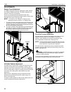
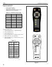
13. Slide cable guide side cover over cable guide making
certain lip on back cover plate is fully seated in groove in
cable guide side cover. (See figure 21)
Figure 21
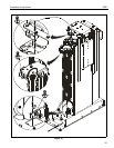
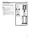
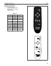
14. Secure cable guide top cover to mount and cable guide side
cover, using two screws.
Figure 22
5
6
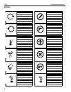
x1
Cable Guide
Side Cover
Back Cover Plate
13
x2
14