To Vacuum Liquids:
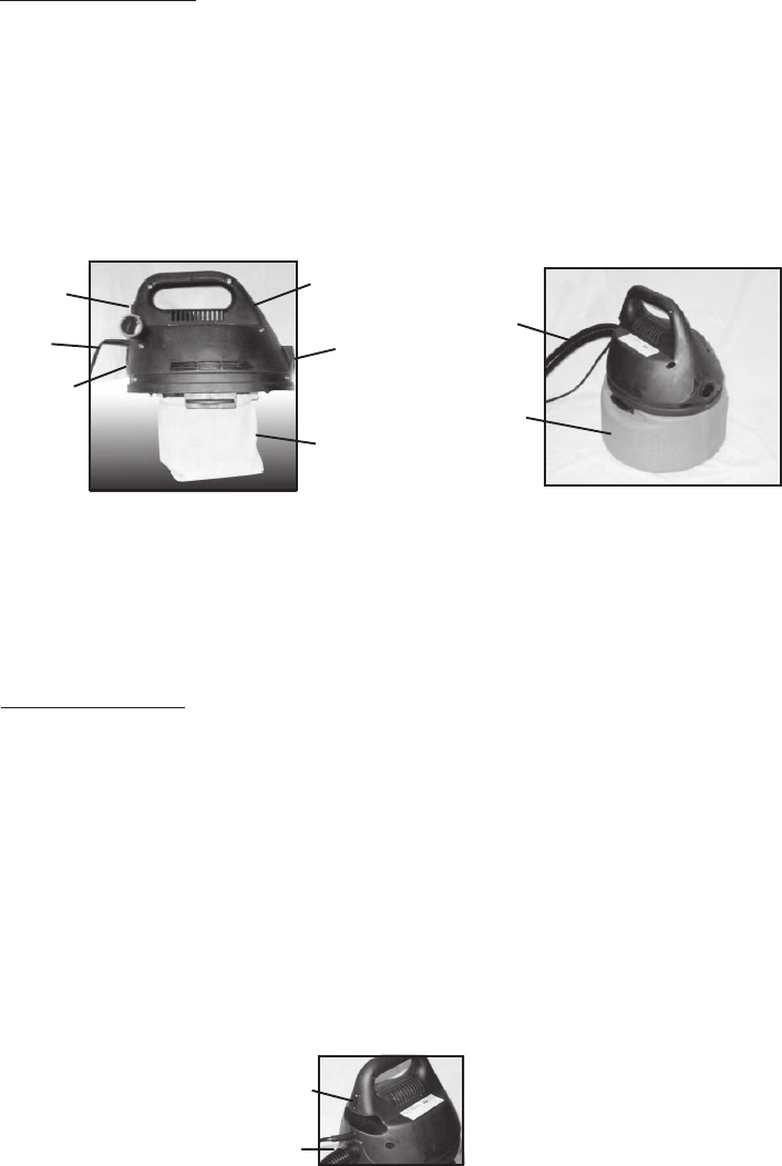
1. For Vacuuming liquids it is necessary to remove the Rubber Band (18) and Bag
(19). To do so, remove the Motor Housing (3) from the Container (20). Empty all
debris from the Container. Remove the Rubber Band (18) and Bag from the Ball
Basket (17).
See Figures A, B, and Assy. Diagram.
2. The Vacuum/Blower is equipped with a Ball (16) which will automatically rise to
cut off the air flow when the liquid in the Container (20) reaches the full level.
When this occurs, make sure your hands and feet are dry, turn “OFF” the
Vacuum/Blower at Switch (1), unplug the Power Cord (4), and empty the
Container.
See Figure B and C.
SKU 90981 Page 6
Switch (1)
Power
Cord (4)
Blower Port
Vacuum
Port
Motor Housing (3)
Bag (19)
Figure B
Container (20)
Figure C
Note: When the Ball shuts off the airflow, the suction increases and the sound of
the Motor becomes higher in pitch due to increased Motor speed. TO AVOID
DAMAGE TO THE VACUUM/BLOWER, DO NOT RUN THE MOTOR WITH THE
BALL IN THE RAISED POSITION.
See Figure A, and Assy. Diagram.
3. When finished vacuuming, make sure to turn the Switch (1) to its “OFF” position
and unplug the Power Cord (4) from the electrical outlet.
To Use The Blower
1. NOTE: The Vacuum/Blower has the capability to blow sawdust, dirt, sand,
leaves, and other debris out of work areas, garages, patios, driveways, etcetera.
ALWAYS wear ANSI approved safety equipment (safety impact glasses, dust
mask, hearing protection) when using the Blower. NEVER point the Hose (21) in
the direction of another person or animal when using the Blower.
See Figures A,
B, C, and Assy. Diagram. Note:
Make certain that the vacuum is clean so that
there will be no dust ejected when the blower is activated.
2. Locate the Blower Port on the Vacuum/Blower, and insert one end of the Hose
(21) into the Port.
See Figures A, B, C, D, and Assy. Diagram.
3. Turn the Switch (1) to its “ON” position to operate the Blower.
4. When finished using the Blower, make sure to turn the Switch (1) to its “OFF”
position and unplug the Power Cord (4) from the electrical outlet.
Hose
(21)
Switch
(1)
Blower
Port
Figure D


