


If the appliance is used to heat a very
small central heating system then the
heat output to the room from the fire
will be reduced. Fig. 3. shows the
ratio of space heating to water
heating which can be expected.
Fitting a radiator in the same room as
the fire is recommended as it will
allow greater flexibility in the way
that the system is operated as well as
ensuring that there is sufficient heat.
Connect the heating system to the
boiler ensuring that the primary flow
pipe rises continuously from the
appliance to the vent. Fill the system
with water and check for leaks.
SYSTEM CONTROLS
Since the controls on the stove are
manually operated we strongly
recommend using high and low limit
pipe thermostats to control the pump.
The high limit, (anti-boiling,)
thermostat, should be fitted on the
gravity flow pipe as near to the boiler
as possible, and the low limit,
(anti-condensation,) thermostat
should be fitted on the gravity return
- again as near to the boiler as
possible but ensuring that it is not on
the common part of the return if only
one return tapping is used. Set the
high limit thermostat at 85°C and the
low limit thermostat at 45°C.
Radiators may be either manually or
thermostatically controlled.
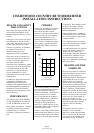
CONNECTIONS TO
FLUES
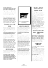
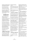
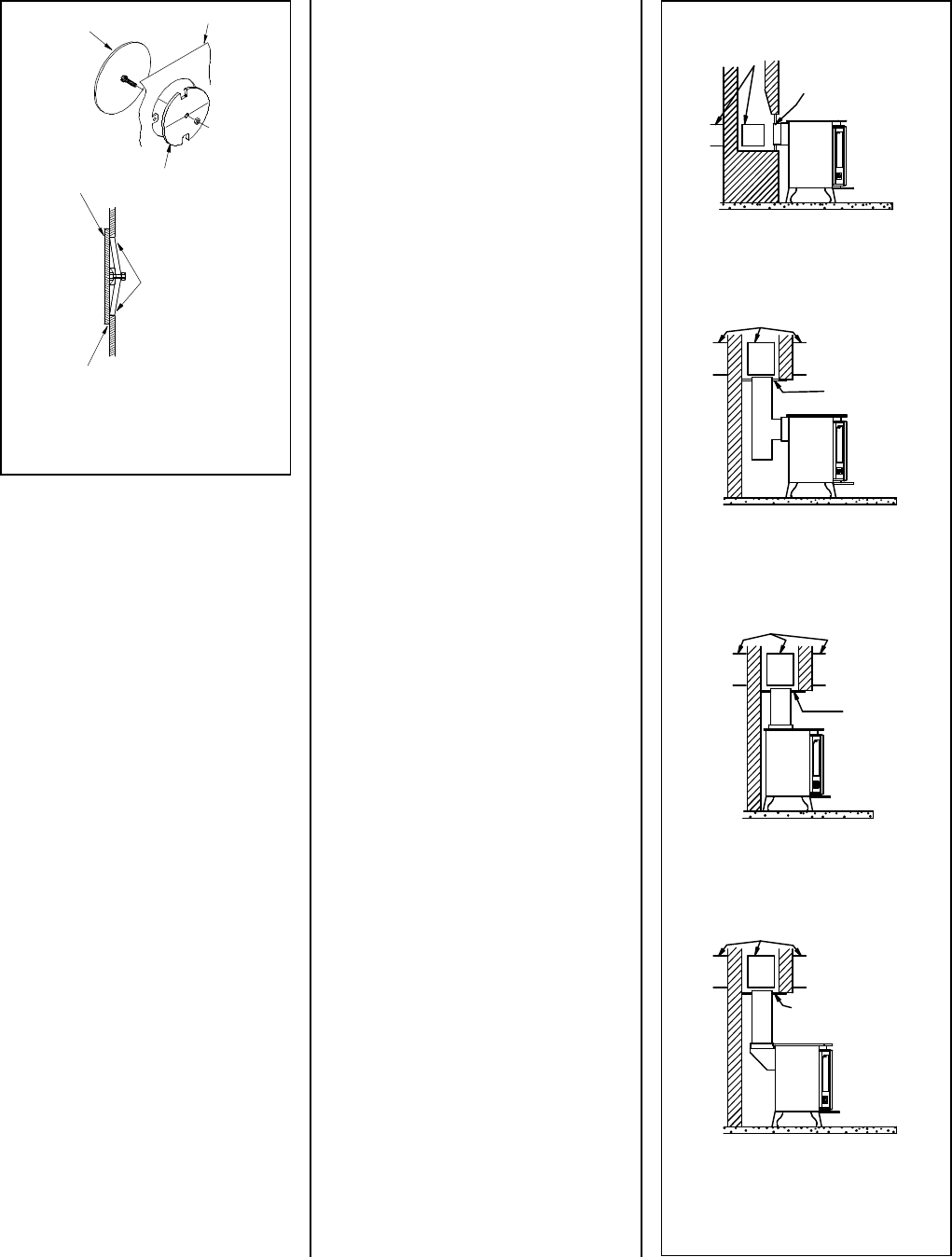
There are several ways of connecting
the stove to the flue. These are
illustrated in Figs. 8 to 11.
If the top flue connection, or the
optional vertical rear flue connector,
is used then chimney may be swept
through the appliance.
Horizontal lengths of flue must be
kept to a minimum and should not be
more than 150mm (6 inches) long.
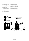
The sealing face of the flue collar
must be coated with fire cement
before fixing to the body of the stove
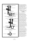
using the two screws provided. The
blanking plate must be removed,
sealed with fire cement and refitted,
care being taken to ensure that the
fold on the blanking plate is in line
with the lugs on the firebox as shown
in Fig. 7. Ensure that the clamping
plate does not prevent the throat plate
from seating correctly. All flue
connections must be well sealed.
SOOT DOORS
It is possible to pass a 16 inch
diameter sweeps brush through the
appliance but in most back outlet
installations it will be necessary to
have a soot door to enable the
chimney to be swept. The optional
vertical rear flue connector does
allow the chimney to be swept
through the stove.
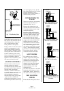
Soot doors may either be in the actual
brickwork of the chimney or in the
register plate. Various positions of
soot doors are shown in Figs. 8 to 11.
PRE LIGHTING
CHECK
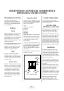
Ensure that the throat plate is fitted
Blanking Plate
Blanking Plate
Clamping Plate
with fold horizontal
Back of the Stove
Clamping plate finishes
flush with inside face of
firebox top and bottom.
with fire cement
Seal Blanking Plate
Fig. 7. Flue Blanking Plate.
With Bricked Up Fireplace
Of Chimney
Soot Door
In Side or Rear
Register Plate
Soot Door
Alternative
Positions
With Top Flue Connection
Soot Door
Alternative
Positions
With Optional Vertical Rear Flue
Connector
Soot Door
Alternative
Positions
Register Plate
With Soot Door
Register Plate
With Soot Door
Register Plate
With Soot Door
With Rear Flue Connection
Fig. 8. Vertical Register Plate
Fig. 9. Horizontal Register Plate
Fig. 10. Horizontal Register Plate
Fig. 11. Horizontal Register Plate
Page 8
Country 8B WB 10/00