


inches) each side and 300mm (12
inches) above the appliance should
give sufficient air circulation. If a
wooden mantelpiece or beam is used
in the fireplace it should be a
minimum of 460mm (18 inches), and
preferably 600mm (24 inches) from
the appliance. In some situations it
may be necessary to shield the beam
or mantelpiece to protect it.
CENTRAL HEATING
SYSTEM
The central heating system must
comply with BS:5449 part 1.
If the system is to be a combined
heating and domestic hot water
system then a double feed indirect hot
water storage cylinder to BS:1556
part 1 should be used. In order to
prevent the build up of scale and
corrosion a suitable inhibitor should
be used. The system must be correctly
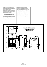
vented as shown in Figs. 4 and 5.
The height differential between the
header tank and the appliance must
not exceed 15.2 metres (50 feet).
If all four boiler tappings are used
then, if possible, diagonal pairs
should be connected for domestic hot
water and central heating. Where a
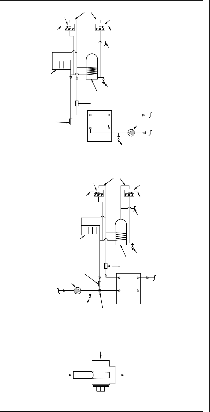
common return is used an injector tee
must be incorporated into the system
as shown in Fig. 6. This will ensure
that a good domestic hot water supply
is maintained when the central
heating pump is operating.
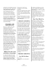
The system must incorporate a
gravity circuit which will normally
heat the domestic hot water and an
unvalved radiator with an output of at
least 1 kW. When the appliance is
not connected to a domestic hot water
system the unvalved radiator(s) on
the gravity circuit must have an
output of at least 1.25 kW. This is to
prevent boiling in case of pump
failure. All pipework in the primary
circuit must be 28 mm diameter and
the gravity flow pipe must rise
continuously from the boiler to the
open vent. Two typical systems are
shown in Figures 4. and 5.
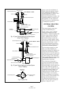
Drain Cock
Indirect Hot Water Cylinder
Gravity Radiator
Domestic Hot Water Draw Off
Cold Water Tank
Overflow
Feed and Expansion Tank
22mm Open Vents
Overflow
Central Heating Flow
Central Heating Return
Drain Cock at Lowest Point
Gravity Return 28mm
Circulating Pump
Thermostat
Using 4 Boiler Tappings
Fig. 4. Typical Central Heating & Hot Water System
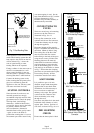
Gravity Return
(28mm Pipe)
Central Heating Return
Common Return to Boiler
(28mm Pipe)
Fig. 6. Injector Tee.
Drain Cock
Indirect Hot Water Cylinder
Domestic Hot Water Draw Off
Gravity Radiator
Cold Water Tank
Overflow
Overflow
Feed and Expansion Tank
22mm Open Vents
Central Heating Return
Drain Cock at Lowest Point
Gravity Return 28mm
Circulating Pump
Injector Tee
Central Heating Flow
Using 3 Tappings
Fig. 5. Typical Central Heating & Hot Water System
Low Limit
Low Limit Thermostat
Gravity Flow 28mm
High Limit Thermostat
High Limit Thermostat
Gravity Flow 28mm
Page 7
Country 8B WB 10/00