breast, one in the front to give access
for infilling and fixing the flue pipe,
and one in the side to give access for
the pipework.
CENTRAL HEATING
SYSTEM
The central heating system must
comply with BS:5449 part 1.
If the system is to be a combined
heating and domestic hot water
system then a double feed indirect hot
water storage cylinder to BS:1566
part 1 should be used. In order to
prevent the build up of scale and
corrosion a suitable inhibitor should
be used. The system must be
correctly vented as shown in Figs. 7
and 8. The height differential between
the header tank and the appliance
must not exceed 15.2 metres (50
feet).
If all four boiler tappings are used
then, if possible, diagonal pairs
should be connected for domestic hot
water and central heating. Where a
common return is used an injector tee
must be incorporated into the system
as shown in Fig. 9. This will ensure
that a good domestic hot water supply
is maintained when the central
heating pump is operating.
The system must incorporate a
gravity circuit which will normally
heat the domestic hot water and an
unvalved radiator with an output of at
least 0.75 kW. When the appliance is
not connected to a domestic hot water
system the unvalved radiator(s) on the
gravity circuit must have an output of
at least 1.0 kW. This is to prevent
boiling in case of pump failure.
If the boiler reduction brick is fitted
then the appliance may be used for
room heating and supplying domestic
hot water without the need for a
gravity radiator.
All pipework in the primary circuit
must be 28 mm diameter and the
gravity flow pipe must rise
continuously from the boiler to the
open vent. Two typical systems are
shown in Figures 7. and 8.
If the fire is used to heat a small
central heating system then the heat
output to the room from the fire will
be reduced. Fig. 4. shows the ratio of
space heating to water heating which
can be expected.
SYSTEM CONTROLS
The circulating pump may be
controlled by means of time switches,
room thermostats or outdoor
thermostats. Radiators may be either
manually or thermostatically
controlled. These controls will all
work in conjunction with the
thermostat on the appliance and the
minimum return thermostat.
We recommend fitting a pipe
thermostat onto the gravity return and
wiring it into the mains supply to the
pump so that if the gravity return
temperature drops below 45°C then
the pump will cut out. This will help
to prevent condensation forming on
the boiler faces and will thereby
increase the life of the boiler. Use of
a minimum return thermostat also
ensures that priority is given to the
domestic hot water. These
thermostats are available from
ourselves if you are unable to obtain
them locally.
FITTING THE FIRE
In some cases it may be necessary to
place the connecting flue pipe in the
chimney before fitting the fire into
the fireplace.
Apply fire cement to the rear face of
the sealing flange on the appliance.
Fit the appliance into the opening
ensuring that it is central and that a
good seal is made between the
sealing flange and the face of the
surround.
Remove any excess fire cement from
around the sealing flange.
The fire should be screwed to the
hearth through the holes at the base
of the sealing flange.
Connect the heating system to the
boiler ensuring that the primary flow
pipe rises from the fire. Fill the
system with water and check for
leaks.
FLUE CONNECTION
AND INFILLING
Make the flue connection with the
special 150° elbow part no.
010/AV12. Please note that this item
is ordered separately from the
appliance. The legs of the elbow may
be cut on site to suit the chimney.
Also note that the legs of the elbow
are different lengths to enable some
situations to be catered for by turning
the elbow around.
The end of the flue pipe must line up
A
B
405mm
400mm
Minimum
This Dimension IsThe
Minimum Level Area
Required To Enable The
For Overall Sizes Of
HearthSeeThe
Section Titled "Hearth".
DoorsTo BeOpened.
Dim.A:
Dim.B:
Min.405mm(16")
660mm
Theshadedarea onthefaceof
thesurroundistheminimumflat
arearequired.
750mm
Min.555mm(21-3/4")
Max.575mm(22-2/3")
Max.470mm(18-1/2")
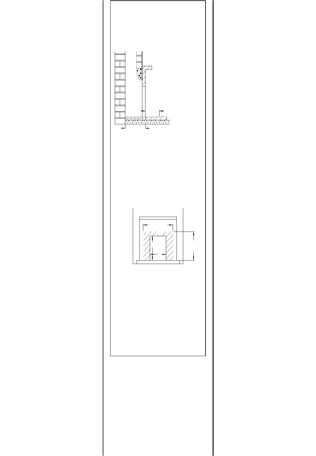
Fig.5.LimitingDimensions
ofHearth
Fig.6.LimitingDimensions
ofSurroundandOpening
Page 8
LA30iB3.99


