


Rev E Doc 01-20201 2 of 33
BASIC INSTALLATION HINTS AND RULES
READ THIS SECTION CAREFULLY BEFORE BEGINNING YOUR INSTALLATION
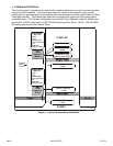
1. UNDERSTAND THE SYSTEM AND INSTALLATION SITE THOROUGHLY. The B3 series are
flexible and reliable gate operator systems, but the quality of service depends directly on the quality
of installation. Please read these instructions and the Installation and Operation instructions for
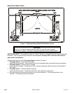
each gate operator carefully. Study the applicable diagrams before planning your installation. In
particular, understand any site characteristics that may affect the system installation.
WARNING
2. INSTALL PERMANENT WIRING. U.L. specifications require the B3 Series Master/Slave systems
to be permanently wired. Refer to your local wiring code for specific information.
WARNING: Damage caused by faulty wiring is not covered by warranty.
3. GROUND THE SYSTEM. The system contains parts which may be damaged by static discharge.
A proper earth ground connected to the housing will significantly reduce the chances of damage or
improper operation. The shielding in the cables specified for all remote sensors and controls should
also be connected to earth ground at the controller end of the cable only.
To be effective, the ground connection must be made by running 12 AWG copper wire to a good
ground point (e.g., an electrical panel, a metallic cold water pipe that runs into the earth, or a
grounding rod at least 10 feet in length that is driven into the earth) within 12 feet of the system.
Even if you have a good ground, you should try to discharge any static before handling the circuit
boards.
WARNING: Damage caused by static discharge and lightning is not covered by warranty.
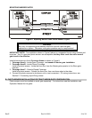
4. PROVIDE POWER FROM A DEDICATED SOURCE. The outlet into which you connect the Gate
Operators should be wired to its own circuit breaker. This will reduce the line noise introduced into
system power and minimize the risk of having other equipment interrupt system operation. In a
Master/Slave system, Master and Slave must each have separate circuits.
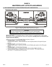
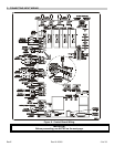
5. DO NOT OVERLOAD THE TERMINAL BLOCKS. The operator’s terminal blocks are removable
and the pins are soldered into the boards. To connect the wires, remove the “head” from the
correct terminals and open the screws. Insert the wire into the correct opening on the front and
tighten the screw until the wire is held firmly. When you have made all connections for a given
“head”, plug it back onto the pins designated for that terminal block.
Stranded wire must be between 16 and 24 AWG. Solid wire must be between 18 and 24 AWG.
This is the total thickness measurement so, if you are putting two wires in, the combined thickness
must fall within this range. NEVER try to insert more than two wires per terminal.
6. ENSURE GOOD CONNECTIONS. A light tug on the wire will tell you if the connection is secure.
When reconnecting system components, make sure all pins are straight on chips, connectors, and
terminal block heads.
7. READ MARKINGS CAREFULLY. The connection points are marked on the boards clearly.
Before making any connection, be sure to read the marking and check it against the corresponding
figure in these instructions so that you understand the connection you are making.
8. TRAIN YOUR CUSTOMERS THOROUGHLY. Although customer responsibility is limited to proper
installation, the quality of service is determined by the care of system set up. Ensure that the
customer has a copy of this manual to guide them. It will save you and them lots of inconvenience
and aggravation later.