


Rev E Doc 01-20201 12 of 33
BIPARTING BARRIER GATES
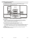
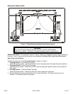
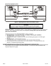
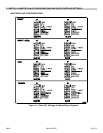
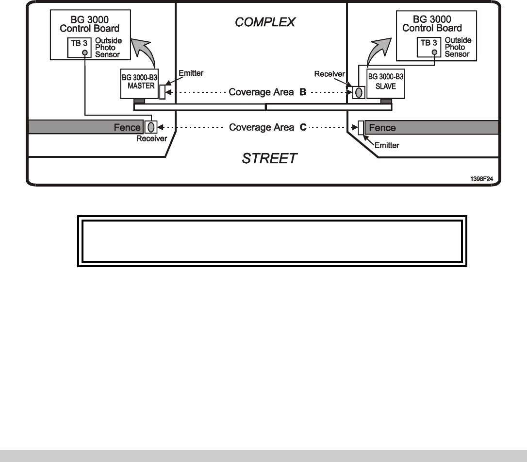
Figure 8. Biparting Barrier Gates Photo-Sensor Layout.
WARNING
Buy only UL-approved photo-sensors made for use with vehicular gate
operators or system. Otherwise, safe gate operation may be compromised.
IMPORTANT NOTE: The installation shown in Figure 8 above is a suggested layout using emitters and
receivers. Any UL-approved photo-sensors are acceptable, but they must cover the entire area of
gate travel to be effective.
Install photo-sensors in three Coverage Areas as shown in Figure 8.
1. Coverage Area A - Inside-Open Coverage: not needed in barrier gate installation.
2. Coverage Area B - Inside-Closed Coverage:
Install one photo-sensor: Inside the fince line, from the Master gate operator to the Slave gate
operator.
3. Coverage Area C - Outside-Closed Coverage:
Install one photo-sensor: Outside the fence line, from one fence edge to the other.
4. Connect the photo-sensors to whichever unit is most convenient. For wiring instructions, see
Section C, Connecting Input Wiring, below.
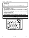
B. PHOTO-SENSOR INSTALLATION FOR TRAP/TANDEM GATE CONFIGURATION
Photo-sensors must be installed on each gate separately. For instructions see the Installation and
Operation Manual for the gates.