


Rev E Doc 01-20201 17 of 33
G. SYSTEM LAYOUTS AND CONTROL WIRING
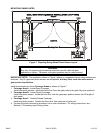
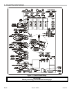
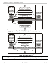
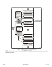
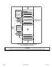
Figure 12. Bi-Part, Bi-Directional Gate System.
NOTE: If Radio is used, only one receiver/transmitter is required for both directions.
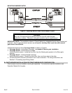
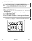
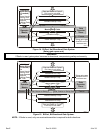
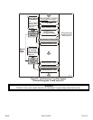
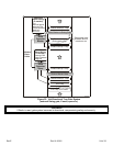
Figure 13. Bi-Part, Uni-Directional Gate System
(Swing gate, if used, opens in).
* WARNING
If Radio is used, gate system becomes bi-directional, compromising safety and security.
Gate
Operator
Master
Gate
Operator
Slave
Directional Exit Loop
Swing gate open
direction and its
maximum arc.
Directional Exit Loop
Can use Radio or Cycle if
Exit Loop is not used.
Inside Interrupt Loop
Outside Interrupt Loop
Slide, Barrier or Swing Gate
Slide, Barrier or Swing Gate
FenceFence
Additional
Master Wiring
(if needed):
Fire
Manual Inputs
Interrupt Bar
Photo-Sensors
MagLock
Warning Relay
Tel . L ine
1398F8
Master/Slave Cable
Shadow Loop
(swing gates only)
Can use Radio or Cycle if
Exit Loop is not used.
Can use Radio or Cycle if
Exit Loop is not used.
Can use Radio or Cycle if
Exit Loop is not used.
Gate
Operator
Master
Gate
Operator
Slave
Exit Loop
Swing gate open
direction and its
maximum arc.
Inside Interrupt Loop
Outside Interrupt Loop
Slide, Barrier or Swing Gate
Slide, Barrier or Swing Gate
FenceFence
Additional
Master Wiring
(if needed):
Fire
Manual Inputs
Interrupt Bar
Photo-Sensors
MagLock
Warning Relay
Tel . L ine
1398F9
Master/Slave Cable
Shadow Loop
(swing gates only)
Can use Radio* or Cycle if
Exit Loop is not used.