


HAVING A PROBLEM? (Continued)
7. Opener noise is disturbing in living quarters of home:
If operational noise is a problem because of proximity of the opener to the
living quarters, Vibration Isolator Kit 41A3263 can be installed. This kit was
designed to eliminate the "sounding board effect" and is easy to install.
8. The garage door opens and closes by itself:
• Is there a neighbor with a garage door opener using the same frequency
code? Change your code.
• Make sure remote push button is not stuck “on.”
9. Door stops but doesn't close completely:
Review Travel Limits Adjustment.
Repeat safety reverse test after any adjustment of door arm length,
close force or down limit.
10. Door opens but won't close:
• Check The Protector System™ (if you have installed this accessory). If
the light is blinking, correct alignment.
• If opener lights do not blink and it is a new installation, check the down
force.
Repeat the safety reverse test after the adjustment is complete.
11. Opener light does not turn on:
Replace light bulb (40 Watts maximum, 230V, E27). Replace burned out
bulbs with rough service light bulbs.
12. Opener light does not turn off:
There may be a defective earth at the ceiling or wall receptacle. The unit
must be earthed.
13. Opener strains or maximum force is needed to activate door:
Door may be unbalanced or springs are broken. Close door and use
manual release rope and handle to disconnect trolley. Open and close door
manually. A properly balanced door will stay in any point of travel while
being supported entirely by its springs. If it does not, call for professional
garage door service to correct the problem. Do not increase the force to
operate the opener.
14. Opener motor hums briefly, then won't work:
• Garage door springs are broken. SEE ABOVE.
• If problem occurs on first operation of opener, door may be locked.
Disable door lock.
15. Opener won't activate due to power failure:
• Pull manual release rope and handle straight down to disconnect trolley.
Door can be opened and closed manually. When the power is restored,
pull the manual release handle toward the opener at a 45˚ angle, so that
the trolley release arm is horizontal. The next time the opener is
activated, the trolley will reconnect.
• The Outside Quick Release accessory 1702EML (if fitted) disconnects the
trolley from outside the garage in case of power failure.
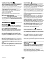
SPECIAL FEATURE OF THE MOTORLIFT 5500
Door within a door connection
Remove cover. Locate auxiliary terminal block. Remove jumper from
terminal leads 1 and 2 (not shown). Replace with magnetic contact switch
leads as shown.
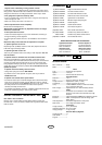
ACCESSORIES
(1) Model 4330EML Single-Function Remote Control
(2) Model 4333EML 3-Function Remote Control
(3) Model 4335EML 3-Function Mini Remote Control
(4) Model 845EML Multi-Function Door Control Panel
(5) Model 75EML Lighted Door Control Button
(6) Model 747EML Wireless Keyless Entry Keypad
(7) Model 760EML Outside Keylock
(8) Model 1702EML Outside Quick Release
(9) Model 770EML The Protector System™
(10) Model 1EML Door Handle Quick Release
(11) Model 34EML 2-Position Key Switch Flush Mount
Model 41EML 2-Position Key Switch Surface Mount
(12) Model 1703EML The Chamberlain Arm™
WIRING INSTRUCTIONS FOR ACCESSORIES
Lighted Push Button: Protector System™:
To opener terminals: To opener terminals:
Red-1 and White-2 White-2 and Black-3
Outside Keylock: Wall Control Panel:
To opener terminals: To opener terminals:
Red-1 and White-2 Red-1 and White-2
REPLACEMENT PARTS
-
SPECIFICATIONS
Max. Pull Force ...........900N
Watts ...........................510W
Motor
Type.............................Permanent split capacitor
Speed..........................1500 rpm
Volts.............................230-240 Volts AC-50Hz Only
Drive Mechanism
Reduction ....................1.27:1
Drive............................Screw. 2 Lead worm. Aluminum rail.
Length of Travel ..........Adjustable to 2,23m (7.4 feet)
Travel Rate..................152mm (6 inches) per second
Lamp ...........................1x230V/40W/E27 socket, on when door starts,
off 4-1/2 minutes after stop.
Door Linkage...............Adjustable door arm. Pull cord trolley release.
Safety
Personal ......................Push button and automatic reversal in down
direction. Push button and automatic stop in up
direction.
Electronic.....................Independent up and down force adjustment screws.
Electrical......................Motor overload protector and low voltage push
button wiring.
Limit Adjustment..........Screwdriver adjustment on side panel.
Start Circuit .................Low voltage push button circuit.
Dimensions
Length (Overall) ..........3,1m (122 inches)
Headroom Required....6cm (2.3 inches)
Hanging Weight...........19 kg (41.8 lb)
Receiver Memory Registers
Computer Code...........12
Code Switch ................1
Keypad ........................1
2726
25
24
6-GB
114A2421D