


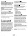

HANG THE OPENER
The opener must be securely fastened to a structural support of the
garage. Attach the hanging brackets toward the front of the opener as
shown (1).
Three representative installations are shown. Yours may be different.
Hanging brackets (2) should be angled (Figure A) to provide rigid support.
On finished ceilings, (Figure B) attach a sturdy metal bracket (not
supplied) (5) to a structural support before installing the opener. For
concrete ceiling mount, (Figure C), use concrete anchors (6) provided.
On each side of opener measure the distance from the opener to the
structural support (or ceiling).
Cut both pieces of the hanging bracket to required lengths. Flatten one end
of each bracket and bend or twist to fit the fastening angles. Do not bend
at the bracket holes. Drill 4,5mm (3/16") pilot holes in the structural
supports (or ceiling). Attach flattened ends of brackets to supports with
wood screws (3).
Lift opener and fasten to hanging brackets with screw, lock washer and nut
(4). Check to make sure rail is centered over the door. REMOVE
25mm (1") board. Operate door manually. If door hits the rail, raise header
bracket.
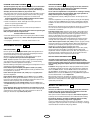
ATTACH MANUAL RELEASE ROPE & HANDLE
Thread one end of rope (1) through hole in top of red handle so "NOTICE"
reads right side up as shown (3). Secure with an overhand knot (2). Knot
should be at least 25mm (1") from end of the rope to prevent slipping.
Thread other end of rope through hole in release arm of the outer trolley
(4). Adjust rope length so that handle is 1,8m (6 feet) above the floor.
Secure with an overhand knot.
Note: If it is necessary to cut rope, heat seal cut end with a match or
lighter to prevent fraying.
CONNECT ELECTRIC POWER
TO AVOID INSTALLATION DIFFICULTIES, DO NOT RUN THE GARAGE
DOOR OPENER UNTIL INSTRUCTED TO DO SO.
Connect the opener to a mains which is properly EARTHED according
to the wiring instruction tag attached to power supply cord (and as
specified by local code).
Connect the door opener only to an outlet controlled by a double pole
switch.
INSTALL THE LIGHTED DOOR CONTROL BUTTON
Locate push buttons where the garage door is visible, away from
door and door hardware and out of the reach of children.
Serious personal injury from a moving garage door may result from
misuse of opener. Do not allow children to operate the lighted door
control button or remote control transmitter.
Fasten the caution label on the wall near the lighted door control
button as a reminder of safe operating procedures.
There are 2 screw terminals (1) on the back of the lighted door control
button (2). Strip about 6mm (1/4") of insulation from bell wire (4). Separate
wires enough to connect the white/red wire to terminal screw 1 and the
white wire to terminal screw 2.
Fasten the lighted door control button to an inside garage wall with sheet
metal screws (3) provided. Drill 4mm (5/32") holes and use anchors (6) if
installing into drywall or concrete. A convenient place is beside the service
door and out of reach of children.
Run the bell wire up the wall and across the ceiling to the garage door
opener. Use insulated staples (5) to secure wire. The receiver terminal
screws (7) are located on the back panel of the opener. Connect the bell wire
to the terminal screws as follows: white/red to 1 and white to 2.
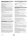
OPERATION OF THE LIGHTED DOOR CONTROL BUTTON
Press to open or close the door. Press again to reverse the door during the
closing cycle or to stop the door during opening cycle.
INSTALL THE LIGHT AND LENS
Install a 40 watt maximum (230V/E27) light bulb (1) in the socket as
shown. The light will turn on and remain lit for 4-1/2 minutes when power is
connected. After 4-1/2 minutes it will turn off.
Replace burned out bulbs with rough service light bulbs (230V/W40/E27).
Apply slight pressure on sides of the lens (2) and slide tabs (3) into slots
(4) in the end panel. Reverse the procedure to remove the lens.
FASTEN DOOR BRACKET
If yours is a canopy or dual-track style garage door, a door arm conversion
kit is required. Follow the installation instructions included with the
replacement door arm. Exercise care in removing and assembling arm
conversion kit. Keep fingers away from the sliding parts.
NOTE: Horizontal and vertical reinforcement is needed for lightweight
garage doors.
Sectional and One-Piece Door Installation Procedure:
1. Center bracket (1) at the top of inside face of door as shown. Mark
holes.
2. A. Wooden doors
Drill 8mm (5/16") holes and fasten the door bracket with nut,
lock washer, and carriage bolt (2).
B. Sheet metal doors
Fasten with sheet metal screws (3).
C. One-piece door optional
Fasten with sheet metal screws (3).
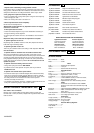
CONNECT DOOR ARM TO TROLLEY
NOTE: For one-piece doors, do not connect door arm to trolley before
adjusting limits. Failure to follow instructions may result in damage to
door. See below.
Sectional Door Installation: Note door arm configuration in Figure B.
One-Piece Door Installation: Procedure (Figure A).
Connect straight door arm (1) and curved door arm sections (2) to obtain
the longest possible length with hardware (3, 4 & 5). With door closed,
connect straight door arm section to door bracket with a clevis pin (6).
Secure with a ring fastener (7).
Before connecting door arm to trolley, adjust travel limits. Limit
adjustment screws are located on side panel.
Open Door Adjustment: Decrease up limit. Turn up limit adjustment
screw counterclockwise 5-1/2 turns.
Press door control button. Trolley will travel to full open position (8).
Manually raise door to open position (parallel to floor) and lift door arm (9)
to trolley. The arm should touch trolley just in back of door arm connector
hole (10) as shown in solid line drawing. Increase up limit if necessary.
One full turn equals 5cm (2") of door travel.
Closed Door Adjustment: Decrease down limit. Turn down limit
adjustment screw clockwise 5 complete turns.
Press door control button. Trolley will travel to full closed position (11).
Manually close door and lift door arm (12) to trolley. The arm should touch
trolley just ahead of door arm connector hole (13) as shown in dotted line
drawing. Decrease down limit if necessary. One full turn equals 5cm (2") of
door travel.
Connect Door Arm to Trolley: With door closed, connect curved arm to
trolley with remaining clevis pin. Secure with ring fastener. Note: Lift door
slightly to make connection if necessary.
Run opener through a complete travel cycle. If door has a slight
"backward" slant in full open position, decrease up limits until door is
parallel to floor.
18
17
16
15
14
13
3-GB
114A2421D